 The air pressure regulator is also known as pressure-reducing valves. Figure 4.21. Fig. Any means of describing flow-generated noise in terms of performance variables in an engineering context should be couched terms of dimensional models [2931,52,53,39,54]. Burscough 51 0 obj<>stream
Flow rate as ratio to critical value as functions of P/P1 for two common valve types (extracted from Ref. A device running at 7 bar will consume twice as much air as it would at 3 bar; so, the use of a pressure regulator, to reduce the working pressure, saves energy and money. In order to calculate the variation of the hydraulic characteristics with the rotational speed for each PAT for both ER modes, the affinity law of turbomachines was applied to the respective nominal rotational speed curve.
The air pressure regulator is also known as pressure-reducing valves. Figure 4.21. Fig. Any means of describing flow-generated noise in terms of performance variables in an engineering context should be couched terms of dimensional models [2931,52,53,39,54]. Burscough 51 0 obj<>stream
Flow rate as ratio to critical value as functions of P/P1 for two common valve types (extracted from Ref. A device running at 7 bar will consume twice as much air as it would at 3 bar; so, the use of a pressure regulator, to reduce the working pressure, saves energy and money. In order to calculate the variation of the hydraulic characteristics with the rotational speed for each PAT for both ER modes, the affinity law of turbomachines was applied to the respective nominal rotational speed curve. Continual investment ensures TRP Polymer Solutions can keep delivering sealing solutions, Discover MGA Controls range of chemical resistant solenoid valves, Automated control of industrial water treatment systems.
0000007034 00000 n Here is a small overview of the basics. A regulator does not need power, instrument air, or any other electronic or pneumatic control devices.
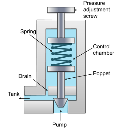
If it is assumed that lossless flow occurs between the upstream region and the vena contracta, then we can integrate the steady equation of motion (Eq. This required a selection process which consisted of a basic preassessment of each PRVs potential for the implementation of a PAT, wherein the head drop defined for the PRV was multiplied by the flow rate, and the 10 PRVs which provided the highest values (QH) were selected for further analysis. 49 34 Spring-loaded pressure-reducing valve. How Does a Pressure Reducing Valve Work? It is often referred to as a pressure regulator. 0000004918 00000 n He provides product and applications training for the Kimrays sales team and customers. 14.7. Output pressure regulation: Desired output pressure setting is an aspect of system design but 100 kg/cm2 (e.g., 35 kg/cm2). As this cycle repeats, liquids continue to fall out of the supply gas into the drip pot where it will need to be drained regularly, depending on the conditions. pressure regulators differential prd regulator valves reducing system plastic open series pp basics filter plastomatic plast matic reduce downstream H\Sn@~\3r*Z[#xiz"%>4$99(^ When the pressure reducing valve is in static state, the steady working pressure of the pressure reducing valve is pL0=p1, and dynamic equations of the valve core are. 0000001768 00000 n By associating the PAT curves to the selected PRVs in the network model, the energy production could be calculated for every year from 2018 to 2033. How does an air pressure regulator works. Each monthly newsletter includesinformation on product improvements, tips on how to better optimize your site, videos and articles on how to complete your own repairs, as well as news about training and events. PRV. T-s diagram for the triple flash system. Fig. However, at a lower pressure, there is less energy in each unit amount of steam produced. 14.10. British Electricity International, in Turbines, Generators and Associated Plant (Third Edition), 1991. The increased downstream pressure will exert more upward force on the diaphragm, causing the plug to move toward closed. A pressure regulator is a type of valve which automatically cuts off the flow of gasses or liquids once they reach certain pressure. To speak with an expert about how a Pressure Reducing High Pressure Control Valve works, contact your local Kimray store or authorized distributor. Swapan Basu, Ajay Kumar Debnath, in Power Plant Instrumentation and Control Handbook (Second Edition), 2019. The steam pressure in the sealing line is indicated in the control room and locally; a fault condition is indicated by low pressure alarms. For example, this can be studied for the single-flash systems by illustrating the turbine power output rates with respect to the potential flashing pressures, which can be considered most suitable for a potential range of pressures between the condenser pressure and the supply pressure in the respective graphs. By Eqs. For each solution the adopted electricity selling prices are 0.057/kWh for the grid connection and 0.098/kWh for the local use, and the discount rate considered is 7.5 percent.
Note that there are two important criteria in determining the pressure to flash the supply water. In this video, were going to look at the production flow through this Pressure Reducing High Pressure Control Valve Package configured with a Diaphragm-Controlled High Pressure Pilot.
For this reason, to be able to perform an energy recovery analysis up to 2033, a network mathematical model was required to calculate these values for each PRV and each year. 0000004514 00000 n
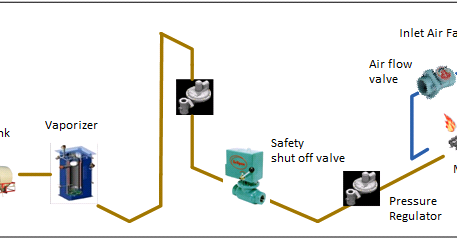
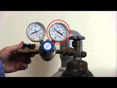
The exiting low-pressure steam/water mixture (or saturated vapor) from the turbine is then delivered to a condenser (C-x) where it exits as the saturated liquid water. Stay ahead of the competition with regular process industry news instalments from PIF. In addition, the T-s diagram of the thermodynamic cycle for a pressure value of 10,000kPa by considering a single-flash unit in the power-generating geothermal system is shown in Fig. The working principle of the air pressure regulator. Hydraulic characteristics of the pressure reducing valves within the Funchal network. pressure reducing does Here, pressure regulators will be used to adjust pressure coming out of an air receiver to match what is required for the desired task.
valve pressure pilot relief operated construction principle working hydraulic line internal If the outlet pressure is below the pressure set by the range spring the valve assembly will stay open until the set pressure is reached. For pressure ratios greater than 1.89, shock waves can be formed in the valve exit and, as discussed in Section 3.4.4 of Volume 1, such flows can generate screech tones. The fluid dynamics of disturbance generation in such valves most probably depends on such parameters as the turbulence intensity in the upstream pipe flow, the geometry of the valve trim, the Reynolds number of the trim flow, and the nature of the structural surfaces just downstream of the valve trim. equilibar hv regulators regulator diaphragm After these modifications, the installation of micro hydro power plants within the system through the use of PATs can further improve the efficiency of the system. A compressed spring generates a force tending to push downward which in turn opens the plug and results in more flow. Since RSS proposed the implementation of 50 different PRVs, there are 50 available locations.
:to|P{ fQlvhf4db / 4]Un1leT :I4^4|UIXLR]D%z YC2LQ* vlZ R%j`k;'Z+uq.4Wh[$ @3RA They are similar to the valve-sizing equations of manufacturers. In some circumstances at large pressure drops across the valve, tones may be emitted because of choked-flow shock formation in the valve trim [50,51]. From: Sustainable Water Engineering, 2020. Examples of air pressure regulators are Masoneilan and Fisher. The valve assembly is moved by the range spring pressing on the diaphragm. Readers wanting a more complete discussion of valve-sizing equations are referred to papers, e.g., by Driskell [55] and Bogar [56]; Reethoff and Ward [57] provide a recent noise prediction method that uses valve sizing parameters. Similarly, it is necessary to increase it from a double to a triple and further from a triple to a quadruple. When the outlet pressure becomes less, the valve assembly opens up to reach the set pressure. 4.22, the upstream static pressure is P1 and the downstream pressure far away from the orifice is P2. Fig. 5.42. During start-up and shutdown, when live steam is used, the pressure at the glands is controlled by the pressure reducing valve in the live steam supply line. Schematic of the triple-flash system with reinjection option. In some compressed air systems, the only pressure control is on the compressor itself - this almost certainly results in too much air consumption and wasted energy and money. regulator frl filter lubricator diagram air system pneumatics flr pneumatic control filters equipment wiring compressor compressed line pressure preparation working 5.41. tameson regulators diaphragm sensing Hydraulic Pressure Reducing Valve for Aircraft, Electro Hydraulic Control Theory and Its Applications Under Extreme Environment, Energy harvesting in water supply systems, Numerical methods make it possible to predict the effect of replacing one or more, Sound Radiation From Pipe and Duct Systems, Mechanics of Flow-Induced Sound and Vibration, Volume 2 (Second Edition), The most commonly used device for regulating gas flow in pipelines is the. Once pressure has vented, and there is no longer enough pressure to overcome the pilot spring, the pilot diaphragm assembly will move back down. Several means of determining optimum flashing pressures for single- and double-flash systems have been previously reported such as Ryley [3], Amiri [4], Selek-Murathan [5], and Dagdas [6]. Recent trends in sizing control valves. It maintains a constant output pressure regardless of variations in input pressure or output flow. Diaphragm-Controlled High Pressure Pilot. 0000012814 00000 n
Thus, the purpose of this case study is to analyse the energy recovery potential of the water distribution system of Funchal (Portugal) through the replacement of PRVs by PATs, ensuring both an adequate pressure management and valuable energy savings and showing the hydropower potential of a real distribution system. Figure 4.23.
The minimum static pressure and the maximum mean velocity of the fluid are attained in the vena contracta. T-s diagram of the quadruple-flash unit in a geothermal power-generating system. Because of turbulence creation downstream of the valve, energy originally in the mean motion of fluid is converted into heat and represents lost momentum. Air pressure regulators are widely used in pneumatics and are used to control the pressure of instrument air, explains Jenny. Berkshire 0000010368 00000 n All these configurations can provide interesting energetic results depending on the water distribution network conditions, presenting a great economic benefit for water utilities if implemented correctly. Once the thermodynamic properties for a potentially optimum pressure in the double-flash systems are known, one can evaluate a triple-flash system for obtaining the optimum first-stage flashing pressure by handling the forthcoming second and third stages as a double-flash system with the first-stage flash pressure as its supply pressure. This compresses a spring, which in turn places the load on the diaphragm assembly. Well also give you an overview of the different types of pressure regulators that are out currently available through Fluid Controls. Now we have answered the question how does a pressure regulator work, it is time to look at the various types of pressure regulators. In this regard, the flashing pressure is herewith calculated as the supply pressure minus the pressure drop. 5.45. 13.14. 13.13B. William K. Blake, in Mechanics of Flow-Induced Sound and Vibration, Volume 2 (Second Edition), 2017. (4.88) shows an increase of Q in proportion to P. pressure regulator stem type figure gauge co2 cylinder regulators moisture sai 0000026462 00000 n Once the adjusting screw is threaded, the spring puts pressure on the assembly which positions the pilot plug to open the flow of supply pressure into the control valve actuator.
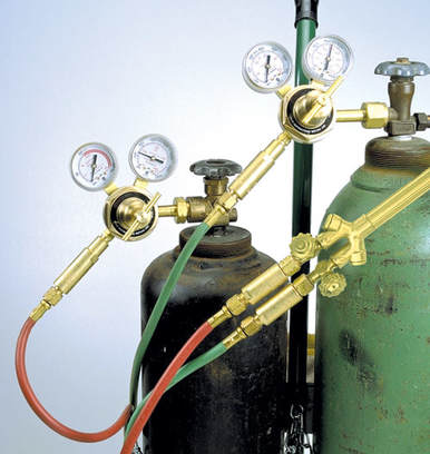
For the process industry, fluid pressure regulators are ideal for use within drinking water systems, as well as pharmaceutical or wastewater applications. The filter removes the dirt particles from the air which may block nozzles etc. A complete analysis of these contributions is out of the scope of this paper, but a comprehensive review can be found in Fecarotta and McNabola [24]. Designers have actually found [56] that an equation similar to (4.91) can be used to approximate Q/Qcrit for typical pressure drops by an empirical valve equation. Figure 4.22. Each of these four types of systems is depicted with their temperature-entropy (T-s) diagrams in the following figures. Outside of the process industry, pressure regulators might be found working alongside air compressors. To study the feasibility of the energy recovery solutions proposed in the WDS of Funchal, an economic analysis was performed for each PAT application separately, considering each mode of operation and storage method. On the bottom of the diaphragm, the outlet pressure of the valve forces the diaphragm upward to shut the valve. Electronic pressure regulators are used to increase and decrease gas pressure to maintain correct pressure, resume Jenny. (4.87) and (4.88) can be used to approximate flow conditions in terms of the pressure drop and the up- and downstream flow conditions.
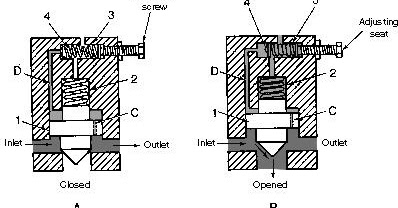
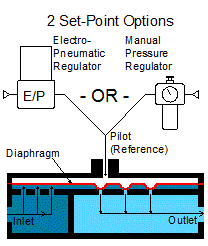
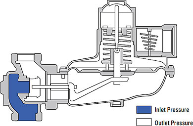
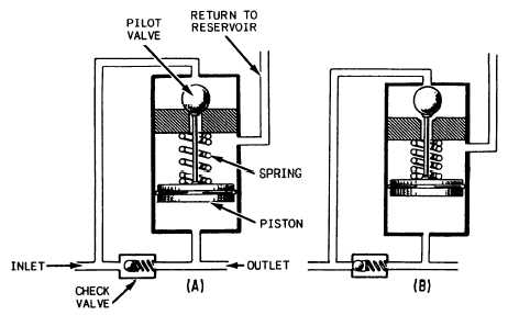
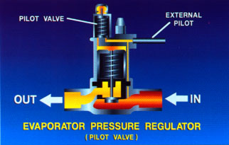
Fig. Fig. One should remember that the most significant thermodynamic property considered for flashing processes in geothermal power plants is the pressure, which needs to be determined optimally for the practical operation of these geothermal-based power-generating systems. 2.2 of Volume 1) together with the equation of state for the gas (following Eq. nozzle instrumentationtools After concluding the PRV selection process and the calculation of hydraulic models, specific PATs had to be selected for each PRV. 0000058829 00000 n This water from the condenser(s) is sent to a pump (P-2) for reinjection back into the geothermal source. So, the main pressure regulator function is to match the flow of gas through the regulator to the demand for gas placed upon it, whilst maintaining a constant output pressure. We now consider a double-flash power-generating system with the respective subunits, which is presented in Fig. Summed up briefly, the nominal speed curves of each PAT have been used as reference curves and alternative rotational speed curves have been obtained through dimensional analysis, treating them as distinct PATs. Once pressure has vented, and there is no longer enough force to overcome the pilot spring, the pilot diaphragm assembly will move back down. Depending on the system design, the inlet pressure of a compressed air system may fluctuate; a pressure regulator will maintain a constant outlet pressure for supply to devices. However, having in consideration that there were 29 different PAT models to choose from and apply to the 10 PRV locations, a digital algorithm has been developed to simulate every possible scenario throughout the years, enabling the development of a fast and detailed testing analysis. Sound power generated in this process increases with the mean flow velocity and the amount of turbulent mixing created. Fig. Pressure regulators are valves that automatically cut off the flow of a gas or liquid when it is at a certain pressure. No supply pressure is available yet to move the valve open. The pressure reducing valve may be used for water hammer protection under properly defined conditions. With this in mind, the primary function of a pressure regulator is to match the flow of gas or liquids through the regulator to demand placed upon the chosen media type. 14.3. The working principle of a pressure regulator is to reduce an inlet pressure (also known as a supply pressure) to a lower outlet pressure type.
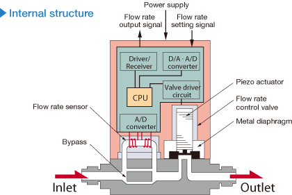
regulator Economic analysis of the optimal hydropower investment in Madeira WSS for grid or stand-alone energy use. Thus an expression for the volumetric flow rate Q is. Our products help improve performance and reduce downtime and energy consumption on production lines across the world. While this function is performed, a digital controller will adjust the timing of the solenoid valve to maintain the pressure point. When the output pressure becomes more than the pressure set by the range spring, the air will go out through the vent.
0000010772 00000 n First, a direct equation can be used to determine the flash pressure as a function of supply pressure. pressure regulator hydraulic fluid regulators figure system pump power hydraulics tpub Finally, the energy production results relative to each possible scenario for every year along with the total accumulated energy from 2018 to 2033 has been calculated. 4.23.
Illustration of a single-flash system with reinjection. Two forces are set up in opposition, and as the balance between the two forces change, different actions take place. Fax: 0118 970 2065, Fluid Controls Ltd is one of the UKs leading distributors for pressure control. Type: Piston type self-regulating for downstream pressure cont. 5.39. This compresses the pilot spring and closes off the flow of supply pressure to the control valve actuator. In this latest article, Fluid controls give you an overview of exactly what pressure regulators are, how pressure regulators work and their typical applications. 50 Easter Park, Benyon Road The process is continuous, maintaining P2 at a set value. These pressures in each step are obviously treated for thermodynamic analysis, assessment, and optimization. 0000011434 00000 n The turbulence produced in the valve trim will have an integral scale, which will be assumed to be proportional to (Ac)1/2. Diagram of flow through a throttling constriction in a tube and the associated static pressure. These include reaction control systems and altitude control systems, due to the presence of corrosive fluids, large temperature extremes and high vibrations. Fluid Controls Ltd is one of the UKs leading distributors for pressure control for a wide range of industries. utilizing this expression simplifies the analysis considerably of some error at low pressure ratios. The presence of FL in one of these expressions denotes that (P)crit is dependent on the valve style. All the while, the pressure regulator will be maintaining a constant output pressure. valve relief pressure working principle construction internal hydraulic setting reservoir spring seat its poppet change screw positioned due At the present state of knowledge, these general models can handle only small hydraulic networks. Power Plant Instrumentation and Control Handbook (Second Edition), Advanced Vehicle Technology (Second Edition), Multiple flashing in geothermal power plants, Thermodynamic Analysis and Optimization of Geothermal Power Plants, Turbines, Generators and Associated Plant (Third Edition), MPC-A, MPC-B, MPC-C and MPC-D/MPB-E, MPB-F and MPB-G. Eqs. 49 0 obj<> endobj trailer As load increases, the steam flow to the HP/IP glands progressively reduces and eventually reverses, as leak-off steam becomes available. 14.1. If we look at the simple diagram below, we see a set screw, spring, diaphragm, and plug. Fig. different (4.87) and (4.90) give a simplified expression for Q in terms of the critical value Qcrit: At low values of P/P1, Q/Qcrit is linearly related to (1/FL)P/P1. Of course, this needs to be done carefully first for the single-flash systems.
A regulator is a classic force balance machine. Now we have answered the question how does a pressure regulator work, it is time to look at the various types of pressure regulators. The reduction of the inlet pressure to a lower outlet pressure is the fundamental characteristics of pressure regulators. An optimum pressure value of the second step in the double-flashing system is the same as that of a single-flash system with the first-stage flashing pressure as its supply pressure. xb```f``c`e`1ab@ !#J Other notable applications for pressure regulators include heating furnaces, mining, welding, gas grills and even medical and dental equipment.
0000009095 00000 n As the diaphragm continues to move upward, the spring is being further compressed, and the downward force it exerts increases. The ball-valve is either in the open or closed position, when the valve is de-energized the ball-valve closes the inlet port and vents the outlet port whereas when energized the ball-valve blocks the vent port and opens the inlet port.
Kyle Andrews serves as Product and Applications Trainer at Kimray.
A pressure-reducing valve (V-x) is used to lower the operating pressure, which causes the flashing of some of the saturated water into the steam as required. This supply pressure moves into the pilot, where the flow is met and blocked by the pilot plug. 5.46. Details of flow structure in the valve trim are complex and valve manufacturers have explored many approaches to noise control over the years. Eq. This pressure will exit the regulator through the outlet air port. Ox>(W This arrangement ensures that only one regulating valve is in control at any one time and that the changeover from live steam to leak-off steam is fully automatic. In addition, the influence of the flashing pressure on both the exergy and quality for 1000kPa saturated water is shown in Fig. regulator pressure theory reducing The plug stops moving toward open and the flow and the pressure are now balanced. Output pressure setting: Wide range from outside.
When the adjustment screw is unthreaded, there is no downward pressure on the pilot diaphragm assembly. Effects of varying flashing pressure on the exergy and quality of steam (1000kPa source). The optimum pressure can be found in one of two ways. Fig. Lancashire
Closure For Pressure Vessel Access Opening. Many industrial applications make use of dangerous gases and liquids. Hydraulic/electronic transmission control system fifth gear, Fig. valve pneumatic principle working diagram regulating seat single film dynamic As air passes down P2 a breathe hole lets air into a chamber below the diaphragm; once pressure either side of the seat is equal, the seat closes with the aid of the sapring. With Reference to Fig.
Adapted from Bogar HW.
Fig. Hydraulic/electronic transmission control system reverse gear. Funchal WDS pilot zone: (A) ground elevation, (B) water demand.
Downstream valve surfaces are important because if the high-speed fluid exiting the construction impinges on a solid surface, a dipole source of noise is created and flow-induced forces will be directly applied to the valve parts. Fundamentally, the valve behavior resembles that of an orifice plate. In this video, were going to look at the production flow through this pressure reducing control valve package, configured with a Bellows Controlled High Pressure Pilot. This also unseats the top of the pilot plug which allows the pressure to vent. The 10 selected PRVs are displayed in Table 13.3 (values correspond to peak discharge conditions).
A Step-by-Step Animation, Lever Operated Piston Balanced Throttling, Pneumatically Operated Diaphragm Balanced, Pneumatically Operated Piston Balanced Throttling, Free Water Knockout Mechanical Three Phase, Horizontal Separator High Pressure Pneumatic Three Phase, Horizontal Separator Low Pressure Mechanical Three Phase, Vertical Separator High Pressure Electric Three Phase, Vertical Separator High Pressure Pneumatic Three Phase, Vertical Separator Low Pressure Electric Two Phase, Vertical Separator Low Pressure Mechanical Two Phase. 0000012188 00000 n
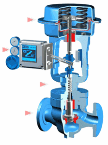
Beginning with the control valve in a closed position and the adjusting screw not yet calibrated to a desired set point, the upstream pressure begins to flowin this example, up to a pressure of 400 PSI. Whereas for the aerospace industry, pressure regulators serve a major role in propulsion pressurant control for many systems. This allows the control valve to travel to its fail position, which in this case is closed. Fig. However, pressure regulators are not just useful within the process industry. Electronic pressure regulating valve current-pressure characteristics, Ron R. Roberts, Greg F. Naterer, in Thermodynamic Analysis and Optimization of Geothermal Power Plants, 2021. However, in the case study of the Funchal water network, only ER operating modes were tested and analysed. You can adjust the downstream pressure by turning the adjusting screw, which varies the spring pressure against the diaphragm. Pressure regulators are one of the most common devices used in both home and industrial applications. Aldermaston These pressure regulators work by passing air from the filtering chamber through the diaphragm and out o the vent. As this cycle repeats, liquids continue to fall out of the supply gas into the drip pot where it will need to be drained regularly, depending on the conditions. An illustration of the double-flash system with reinjection. A factor. A plot shows the maximum with a corresponding optimum flashing pressure. Material: 316 SS body and internal/wetted parts. 13.13. Interested in receiving even more industry-leading news from Process Industry Forum delivered directly to your inbox? 0000019858 00000 n 14.9. The spring-loaded pressure-reducing valve (Figure 7-15) is commonly used in pneumatic systems. The water demand distribution is reported in fig. 0000001571 00000 n The T-s diagram of the cycle for 10,000kPa under a triple-flash system is illustrated in Fig. Browse our range of pressure regulators to find out more, Please select your region, country and language, Norgren Ltd, Blenheim Way, Fradley Park, Lichfield, WS13 8SY. Pressure regulators are one of the most common devices used in both home and industrial applications. then the PRV (both high- and low-capacity) will be closed. Therefore, maintaining a controlled pressure to avoid leakage or even explosion is imperative. We use the set screw to show the regulator how much pressure we want by turning it to compress the spring. Moving from a single- to a double-flash system requires a careful thermodynamic analysis and optimization. 0000008467 00000 n 14.8. Beginning with the control valve in a closed position and the adjusting screw not yet calibrated to a desired set point, the upstream pressure begins to flow in this example, up to a pressure of 400 PSI. Consequently, the rise in pressure at the glands causes the live steam pressure regulating valve to close progressively, thus maintaining a constant supply pressure at the glands and eventually closing completely. As P approaches the critical value for a given valve, Q becomes equal to Qcrit, as illustrated in Fig. One of their most popular uses is in air compressors, where they are used to adjust the pressure coming out of an air receiver to match what is needed for the task.
The steam sent to the turbine(s) is used to generate power. Pressure regulators are found in many common home and industrial applications, including heating furnaces, gas grills and even medical and dental equipment. To evaluate the economic benefit, two scenarios have been considered, differing for the use of energy, i.e. This supply pressure pushes up on the control valve diaphragm working against the tension of the spring. Firstly, it is important to stress that a pressure regulator is NOT a flow controller; these are two different animals.
horiba stec characteristic semiconductor Fig. 0000005011 00000 n 13.13A, the pipeline and the terrain elevation distribution are reported, showing very high ground slopes in large parts of the network.