Hence the need to follow a suitable procedure when designing your fan (a driven impeller within a casing). Fans' calculations are based upon all the entrained air passing through the impeller with each rotation, which is normal practice for optimum blade configurations. centrifugal blower animation fan fans inline radial rebel duct quiet powerful ; If you are using metric units, you may find it simpler to use metres and kilograms and for Imperial calculations, you should find it easier to use feet and pounds (avoirdupois) as the gas constant is readily available in these units. 520 0 obj<>stream
Multi-stage fans are normally used to increase outlet pressure, but are comparatively expensive. However, frictional and directional losses from the casing invariably reduce output efficiency. 0000092243 00000 n
: raises L and lowers L
0000003790 00000 n
For a few industries, dirt assortment is necessary a part of their operations, also as being legal. However, by charging the fan with air, it will naturally generate a localised vacuum at the inlet side, and the greater movement of air outside the fan will normally generate higher positive pressure than atmospheric for the fan to overcome. A simple calculation procedure you may use to establish the output flow rate of the fan (impeller inside a casing) is provided in the calculators technical help menu. your fan will not actually achieve the desired/calculated flow-rate and/or pressure. 770 0 obj
<>stream
However many blades you decide to install, you should ensure that they should not overlap. If you get it wrong, the results will be meaningless, not just theoretically meaningless but practically also. Dust loading industrial blowers collect dirt to boost air quality. %PDF-1.5
%
LTD. - WATER TREATMENT COMPANY DELHI/NCR, J-176, SECTOR-41, NOIDA, Gautam Buddha Nagar, Uttar Pradesh,India, 201301. This does not mean Innes' theory doesn't work, it means that the air will not flow over the fan correctly.
6mSR!zUe~a9PPW PFA0SK!Lj
BP4W.2a C3^ 2"Q#ZV0&0^fI)[*j123YrvADkoB*f@`!XR-`
V,@! 3,* H;3sD RSW
A few rules:
Within closed system, air filtration systems, and collectors like baghouses, traps, and ductwork are found. Like all theories it requires you to follow a few basic rules. trailer
If this angle is less than '' a warning will appear to increase its value, is the length of the blades between the inlet and outlet edges in an axial fan, w is the width of the blades in a centrifugal fan, parallel to the axis of rotation of the impeller, is the density of the air at the inlet edge of the fan blades, p is the pressure of the air at the inlet edge of the fan blades, T is the temperature of the air at the inlet edge of the fan blades, R is the specific (or mass) gas constant, F is the coefficient of friction of air (with the blades).  0000010741 00000 n
volute centrifugal scirp L: lower , N and raise ,
the difference between the inlet and outlet pressures plus the velocity pressure, ps is the static pressure in the fan; i.e. This value must be set to 1 (one) if p is in units of mass per unit area such as kgf/m or lbf/ft. Common Output Data (immediately prior to outlet diffuser of the fan casing): Pc is the expected power required to drive air through the outlet casing diffuser (incl. fan centrifugal blades blade types blower curved backward forward fans impellers figure 240z ventilation 1972 both cibsejournal dust each fan in the sequence increases pressure over the previous fan until you have achieved the pressure required. p = 103858N/m). Now with the help of an example, we will understand impeller speed of air blower: = 0 Ze (we are dealing with air, so elevation head is negligible compared with pressure and velocity heads). CalQlata has tried to keep the operation of this calculation option as simple as possible, given that it is recommended for general purpose calculations only and not for actual purchase specifications (see Fan Calculator Technical Help below). The fan calculator will recognise the correct value; i.e.
0000010741 00000 n
volute centrifugal scirp L: lower , N and raise ,
the difference between the inlet and outlet pressures plus the velocity pressure, ps is the static pressure in the fan; i.e. This value must be set to 1 (one) if p is in units of mass per unit area such as kgf/m or lbf/ft. Common Output Data (immediately prior to outlet diffuser of the fan casing): Pc is the expected power required to drive air through the outlet casing diffuser (incl. fan centrifugal blades blade types blower curved backward forward fans impellers figure 240z ventilation 1972 both cibsejournal dust each fan in the sequence increases pressure over the previous fan until you have achieved the pressure required. p = 103858N/m). Now with the help of an example, we will understand impeller speed of air blower: = 0 Ze (we are dealing with air, so elevation head is negligible compared with pressure and velocity heads). CalQlata has tried to keep the operation of this calculation option as simple as possible, given that it is recommended for general purpose calculations only and not for actual purchase specifications (see Fan Calculator Technical Help below). The fan calculator will recognise the correct value; i.e.  It is inadvisable to significantly orientate the outlet tip of an impeller blade in a forward direction ( > 110) as it would disrupt airflow and give unreliable results. 2 0 obj
As can be seen in Fig 8; the following input data produces comparable results with a data-sheet issued by a prominent manufacturer for one of its fans:
Outlet blade angles greater than 90 will always give you a bit of a challenge to create a workable solution.
It is inadvisable to significantly orientate the outlet tip of an impeller blade in a forward direction ( > 110) as it would disrupt airflow and give unreliable results. 2 0 obj
As can be seen in Fig 8; the following input data produces comparable results with a data-sheet issued by a prominent manufacturer for one of its fans:
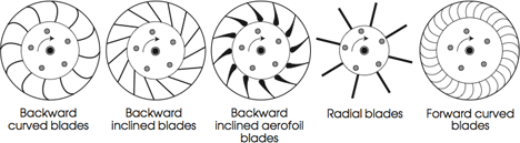
Outlet blade angles greater than 90 will always give you a bit of a challenge to create a workable solution.  As shown in Fig 5, except for very specific performance requirements, there is little to be gained in designing a centrifugal impeller with blade tip angles greater than 90. v and v: the absolute velocity of the air at the inlet and outlet edges of the blade and will vary from inlet to outlet for both axial and centrifugal fans. p = p .v. {use '+' if the direction of movement is towards the fan and '-' if it is moving away from the fan}, Velocity Pressure; is the pressure generated by the gas moving through the fan, Discharge Pressure; is the sum of the velocity pressure and the difference between the outlet pressure and the inlet pressure (Fig 2), Static Pressure; is the maximum of the inlet and outlet pressures, Pressure Head; is the head generated by the discharge pressure at the outlet side of the fan, The shape of your blades and the direction they travel will define the performance characteristics of your fan. : lowers L and raises L
rotodynamic pumps diffuser impeller volute discharge flow stage pressure piping increasing further direct another system into 0000009002 00000 n
As shown in Fig 5, except for very specific performance requirements, there is little to be gained in designing a centrifugal impeller with blade tip angles greater than 90. v and v: the absolute velocity of the air at the inlet and outlet edges of the blade and will vary from inlet to outlet for both axial and centrifugal fans. p = p .v. {use '+' if the direction of movement is towards the fan and '-' if it is moving away from the fan}, Velocity Pressure; is the pressure generated by the gas moving through the fan, Discharge Pressure; is the sum of the velocity pressure and the difference between the outlet pressure and the inlet pressure (Fig 2), Static Pressure; is the maximum of the inlet and outlet pressures, Pressure Head; is the head generated by the discharge pressure at the outlet side of the fan, The shape of your blades and the direction they travel will define the performance characteristics of your fan. : lowers L and raises L
rotodynamic pumps diffuser impeller volute discharge flow stage pressure piping increasing further direct another system into 0000009002 00000 n
<>
This value is zero for axial fans and sometimes ignored in head (H) and efficiency () calculations for centrifugal fans. In order to lower
However, the results are sufficient to validate Charles Innes' theory, on which Fans is based. L is the loss of head due to the air changing direction as it enters the fan. Even forward facing blades should have inlet angles <90 {'forward facing' refers to the outlet angle only}, is the angle of the outlet tip of the blade which can only be between 0 and 180. Ac is the cross-sectional area of the casing diffuser
Mechanical/electrical efficiency must be dealt with by the designer when selecting suitable materials and drive systems.  In this case, the outlet area should be no less than that of the impeller blades. 0000009673 00000 n
Your impeller won't work. Copy and paste into your spreadsheet for plotting (see Fig 8). 5) If you are getting negative results, this simply means that your head losses are greater than the head generated. 3 Blades: Excellent for impellers with small aspect ratio (e.g. all of which have individual benefits (volume, pressure, speed, power, efficiency, etc.) 1.05 bar represents unusually high pressure and may be ignored for general applications. The drive system and casing irregularities are difficult to incorporate in a calculator as the possible variations are infinite. The following table summarises the characteristics you can expect from your fan dependent upon the shape of its blades (Fig 3). impeller). ?Rji~fhx*tbqIx/)FTp`F0of"3R
7v9oN'PWN6JUv6>0R7F. 0000002654 00000 n
0000005052 00000 n
The leading (inlet edge) angle can be set to eliminate this shock resulting in v=0. centrifugal impellers 6 Blades: Losses from increased skin friction and mass begin to exceed airflow gains. You may ignore this value if you're not interested in determining the gas-change rate as this is the only calculation where it's used. hb```f``jc`a``d@ A+s\ageee:1g$ \;viSG.oT"b'frvfL;qCGrGGGdHdG@vH 8X$AQm##7K-|v@L.sqKMa(qAa 0000006136 00000 n
You should be careful when selecting your units as your gas constant (R) will dictate the units of mass and length for all your output results, i.e. 5 Blades: Best configuration for all medium aspect ratio impellers. centrifugal impeller tangential calculations centrifugal
In this case, the outlet area should be no less than that of the impeller blades. 0000009673 00000 n
Your impeller won't work. Copy and paste into your spreadsheet for plotting (see Fig 8). 5) If you are getting negative results, this simply means that your head losses are greater than the head generated. 3 Blades: Excellent for impellers with small aspect ratio (e.g. all of which have individual benefits (volume, pressure, speed, power, efficiency, etc.) 1.05 bar represents unusually high pressure and may be ignored for general applications. The drive system and casing irregularities are difficult to incorporate in a calculator as the possible variations are infinite. The following table summarises the characteristics you can expect from your fan dependent upon the shape of its blades (Fig 3). impeller). ?Rji~fhx*tbqIx/)FTp`F0of"3R
7v9oN'PWN6JUv6>0R7F. 0000002654 00000 n
0000005052 00000 n
The leading (inlet edge) angle can be set to eliminate this shock resulting in v=0. centrifugal impellers 6 Blades: Losses from increased skin friction and mass begin to exceed airflow gains. You may ignore this value if you're not interested in determining the gas-change rate as this is the only calculation where it's used. hb```f``jc`a``d@ A+s\ageee:1g$ \;viSG.oT"b'frvfL;qCGrGGGdHdG@vH 8X$AQm##7K-|v@L.sqKMa(qAa 0000006136 00000 n
You should be careful when selecting your units as your gas constant (R) will dictate the units of mass and length for all your output results, i.e. 5 Blades: Best configuration for all medium aspect ratio impellers. centrifugal impeller tangential calculations centrifugal
making the axial fan more efficient, primarily due to the negligible losses from shock and outlet energy that are always present and need to be optimised in centrifugal fans.
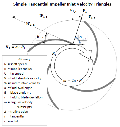
H is the pressure-head of the fan after removing the effect of the operational losses (L, L, L), is the efficiency of the airflow through the fan based upon the loss of head (excluding mechanical efficiency), is the efficiency of the airflow through the fan based upon the loss of head, ignoring loss due to inlet shock (L) (excluding mechanical efficiency), is the isentropic efficiency of the airflow through the fan, v is the absolute velocity of the air at the inlet edge of the blades, v is the absolute velocity of the air at the outlet edge of the blades, v is the axial (AXIAL FANS) or radial (CENTRIFUGAL FANS) velocity of the air at the inlet edge of the blades. methodology furnace numerical validation structural coil The number of blades (in your impeller) does not affect Fans' calculation results. You should therefore apply the relevant performance specification of your preferred supplier's product to your final design as opposed to your design requirements. It is therefore necessary to play with these to achieve the desired results. 0000002000 00000 n Industrial blowers are either centrifugal, axial, or positive displacement. <]>> 0000005758 00000 n N: raises L and L propeller Power will increase with material mass & drive mechanism inefficiencies, and the head and flow rates will vary with casing design. 0000011380 00000 n 2) Use Fans to size your impeller and set your blade angles. Whilst a fan's efficiency is not the only consideration for a designer, performance being his/her primary concern, it should not be ignored. endobj Axial: = 100%; H = 15.5m; P = 268W; p = 202Pa L=0 A comparison between the efficiency and performance of equivalent Axial and Centrifugal impellers is provided below For example the theory assumes a smooth transition from inlet blade tip to outlet blade tip. impeller speed: N = 2685 {RPM} 2) Paddle blades must be 90 inlet and outlet (not simply close to this value) as they do not drive the air using the blade profile, they drive air out through the impeller using centrifugal force and any other angle will create unnecessary back pressure, 3) Always use inlet blade angles considerably less than 90. Fig 7 is a breakdown of air velocities for each of the three available blade configurations. There are a number of fan types: impeller, axial, centrifugal, Sirocco, etc. 0000007742 00000 n %PDF-1.5 You will find further reading on this subject in reference publications(3 & 12), Fig 8. centrifugal sciencedirect V is the volume of a room or space that your fan must affect a gas-change rate (V). 0000012104 00000 n 482 0 obj <> endobj It is based upon the velocity of air as it passes over the blade profile (Fig 3). axial fans) and much simpler to balance than 1 and 2-Blade designs. <>/Font<>/ProcSet[/PDF/Text/ImageB/ImageC/ImageI] >>/MediaBox[ 0 0 612 792] /Contents 4 0 R/Group<>/Tabs/S>> 0000002628 00000 n The blade-tip angles define a fan's performance. xbbb`b``3 1 | lateral channel blowers absolute assembled impeller rotating balanced dynamically ensure shaft directly almost motor parts gugliotta This is often achieved through the utilization of a system of blowers and fans. As long as the cross-sectional area of a fan's diffuser (outer casing; Ac) is greater than the surface area of the outside diameter of the impeller (A or Ao for axial and centrifugal respectively), the fan will exhaust 100% of volumetric flow with the same pressure variation as generated by the impeller (p). endobj The two blade tip angles define the profile of your blade. The manufacture of saturated air industrial blowers needs customized blower blades which will perform in wet environments. Importance of controlling nitrate in drinking water, Recycling of rejected with RO water plant in breweries, What can be the possible solution to prevent sewage flow into water, WWTP for Semi-conductor manufacturing industries, NETSOL WATER SOLUTIONS PVT. If you need to include losses in addition to the efficiency of the fan () you can incorporate them by multiplying the expected additional losses by the efficiency factor and entering the modified value for in the input data, Q is the mass flow rate of gas through the fan, Q is the mole flow rate of gas through the fan, v is linear velocity of the gas through the outlet aperture, and are the input and output densities of the gas (respectively) passing through the fan, p is the velocity pressure of the gas passing through the fan, i.e. v and v: the centrifugal velocity component of the air will be zero for the inlet edge of an axial fan blade and will vary from inlet to outlet for both axial and centrifugal fans Fans calculates the airflow through an impeller together with the expected effects a restricted casing diffuser would generate. # blade angles: forward facing (backward facing).
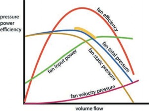
Q is the volumetric quantity of gas {m} you want to shift through the fan every second. This calculation option determines the airflow through impeller blades. This figure will be higher for an impeller in a casing (i.e. 0000004012 00000 n <> CalQlata suggests that, unless you have actual or more accurate data for the pressure differentials between inlet and outlet you could estimate these pressures as follows (Fig 6): p: Calculate the flow rate, setting the inlet and outlet pressures both equal at 101,322.5N/m. The greater the outlet blade angle the shallower must be the inlet tip angle. Air movement is achieved by massive angle blades connected to the hub of the blower. fan curve curves duct flow axial hood fans air stove pressure performance system resistance inlet different rate blowers typical requirements 67). 1) List your operating parameters (flow-rate, head, pressure-rise, etc.). This has a higher speed value efficiency. This problem can be overcome simply by altering the outlet angle to 89.99. stream 0000004261 00000 n They do this by rotating a series of angled blades (or vanes) that pull the air through an aperture.
1) Always try to use a backward facing blade where possible. gravitational acceleration: g = 9.80663139 {m/s} With particular regard to centrifugal fans; the impeller inlet area should be no less than the inlet area of the blades; ./4 ..w. If all input data is correct and accurate, there is no expected error margin in the results. 5) Output area of the impeller is ..w It is now considered to be the industry standard and has stood the test of time since 1916. This value is equal to 'v' in axial fans, v is the velocity outlet side of the blades. Moreover, it is advisable to minimise the number of blades used in such fans. 0000004305 00000 n v and v: the speed of the air over the surface of the blade will vary from inlet to outlet for both axial and centrifugal fans It does not calculate a fan's mechanical efficiency. _Xy4#%im| H31np &,Pu C air) passing through the fan, p and p are pressures of the gas at the inlet and outlet sides of the fan respectively, is temperature of the gas at both the inlet and outlet sides of the fan, P is the minimum power of the fan (e.g. it is advisable to minimise the number of blades in high flow-rate fans. startxref In other words; increasing: See Calculations above. You may enter this value as a factor (e.g. You may use any units you like, but you must be consistent. 3) fettle both tip-angles (inside and outside) to finalise your results. To produce the required results of removing saturated air, custom industrial blowers created that corrosion and rust resistant, which suggests the utilization of chrome steel or metals coated in an exceedingly wet resistant epoxy. )\njg1P~%71 F 8 @F u:X>ul~~p/_~XP7>{u)a?9T BaOc?F{X>q_Z+~ *%-UTX#}%cmQkKdl~=n74C1W-9D:[2elo^GSbLMzV'r3j `""0cn UvO1`+u+0$BFQv:g : lowers L and raises L, N is the rotational speed of the fan blades in revolutions per minute, is the angle of the inlet tip of the blade which can only be between 0 and 180. For the purposes of this description; the outlet area of a diffuser is the orifice furthest from the impeller.
the lower the air resistance, the faster the rotation and the greater the flow. L: lower , N, and raise Whilst it can be difficult to recalculate a manufacturer's working fan if most of the input data is unknown, it can be reproduced by playing with the blade tip angles ( & ). 0000008372 00000 n xb```b``Sa`c`gd@ AV(GL)a*k%00lq C,F$KE,0y-=7Iec An industrial blower could be a device that enhances the air flow in an exceedingly effectively and expeditiously by using an electrical motor, impeller, and air foils. it is entirely up to you as to how many blades you use in your impeller. Every manufacturer's product will differ in terms of performance and specification to every other manufacturer. 730 0 obj <> endobj The two calculation examples in Fig 8 both took the same time to reproduce (5-minutes), but the backward-blade calculation was easier to match in the time allotted.