The limit switch: TOUCHED To rotate in anti-clockwise just enter the number with negative sign. The A4988 driver has total of 16 pins which are as follows: 1. The DIR pin will control the rotation direction and the STEP pin will control the steps. So you will be directed to NextPCB website. NEMA 17 Stepper motor is generally used in Printers, CNC machines and Laser Cutters. In the previous tutorial we learned Controlling the Stepper Motor with Potentiometer and also with Joystick. One such motor acts as the paper feed, spinning rollers that move the piece of paper as ink is being printed on it. This program drives a unipolar or bipolar stepper motor. You can enter any desired values, like entering 1will make the motor to take only one step. First we know that it is a 5V Stepper motor since we energize the Red wire with 5V. The number of steps to be moved will be provided by the variable val. If you think the video tutorials are essential, please subscribe to our YouTube channel to give us motivation for making the videos.if(typeof ez_ad_units != 'undefined'){ez_ad_units.push([[728,90],'arduinogetstarted_com-leader-4','ezslot_9',106,'0','0'])};if(typeof __ez_fad_cmd != 'undefined'){__ez_fad_cmd.push('div-gpt-ad-arduinogetstarted_com-leader-4-0');}else{ __ez_fad_cmd = ['div-gpt-ad-arduinogetstarted_com-leader-4-0'];}; How to stop stepper motor when a limit switch is touched, How to change the direction of stepper motor when a limit switch is touched, How to change the direction of stepper motor when two limit switches is touched. Inside the L298N chip, youll find two standard H-bridges capable of driving a pair of DC motors or a single stepper motor. There are numerous varieties of stepper motors. It is rated for 2 A per coil with sufficient additional cooling. It is important to know how to calculate the steps per Revolution for your stepper motor because only then you can program it effectively. If the wiring is correct, you will see the motor spins in the clockwise direction. Now lets connect the A4988 Stepper Motor driver to Arduino and control NEMA17 Stepper Motor. For me is more difficult because, I can send only one parameter(one of them), Submitted by gvg on Tue, 07/24/2018 - 00:07. All rights reserved. The motor is attached to digital pins 8 - 11 of Arduino. 
 If you have any doubts post them on the comment section below our on our forums., #include
 // Include the header file, // change this to the number of steps on your motor However, it is always recommended that you consult the datasheets and guides of the motors and drivers specific to the models you have. The motor will take one revolution in one direction, then one revolution in the other direction. In Arduino we will be operating the motor in 4-step sequence so the stride angle will be 11.25 since it is 5.625(given in datasheet) for 8 step sequence it will be 11.25 (5.625*2=11.25). When the jumper is removed, the 5V regulator is disabled and we have to separately supply 5V through the VSS pin. The stepper motor is STOPPED If you want to control the motor programmatically, you need to remove the jumpers and connect those pins to the digital pins on the Arduino. This sketch controls both the speed, the number of revolutions, and the spinning direction of the stepper motor. This is where the stepper motors come in handy. In this Arduino tutorial, We are going to learn how to use Arduino, limit switch, L298N driver and stepper motor. The constructor of the Stepper class takes the steps per revolution of the motor and Arduino pin connections as arguments. Since we have 32 steps and 64 as the gear ratio we need to move 2048 (32*64=2048), to make one complete rotation. arduino projects stepper motor electronics engineering diy So 3v is just the lowest possible voltage to achieve the current needed to move motor. The video which shows the sequence of energization can be found at the end of this tutorial. Hey, thanks a lot! That is the reason of using the driver circuit. The L298N module has a total of 11 pins that connect it to the outside world. Thanks for sharing, Submitted by Shahroz Shabbir on Tue, 10/31/2017 - 09:59. seems good (Y) and simple concept explained well. 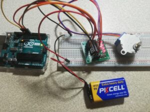 What will damage the motor is current (Amperes). IP22 rated medical & home-healthcare 18/24/36W AC-DC adaptors with interchangeable AC plugs. stepper code arduino motors drive transistor Next, we need to supply 5V to the logic circuitry of the L298N. To energise the four coils of the stepper motor we are using the digital pins 8,9,10 and 11. The way you pulse these pins affects the behavior of the motor. The circuit Diagram for the arduinostepper motor control project is shown above. Polarity doesnt matter. Share the Joy of learning with us. Therefore we need Stepper Driver Module like A4988 or DRV8825. // create ezButton object that attach to pin A0; // without this part, the move will stop after reaching maximum position, // if motor moved to the maximum position, // move the motor to maximum position again, // without calling stepper.run() function, motor stops immediately, // NOTE: stepper.stop() function does NOT stops motor immediately. If the wiring is correct, you will see the motor rotates clockwise direction. At the center of the module is a big, black chip with a chunky heat sink the L298N, from ST Semiconductor. In our case it is 200. arduino wiring stepper diagram uno bipolar motor circuit using bridge tutorial examples cc driver fritzing drive example driving control 12v
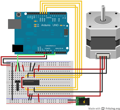
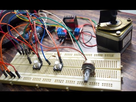
  As the name suggests it is the number of steps per revolution that your motor is rated at. Can you clarify what capacitor should be used for the 5v power supply? Please note that step() is a blocking function. Orange - Pin 11, Submitted by Aswinth Raj on Wed, 03/07/2018 - 11:30, In reply to Circuit Diagram is Incorrect by Michael MacDonald. Then, we also know that it is a four phase stepper motor since it had four coils in it. Let us take a look at the coils present inside the motor to know exactly know from where these wires come from. DO you need to download the stepper.h file my code wont compile. Thus, we can control the stepper motor with just 2 pins from our controller. Submitted by Manuel on Sat, 04/14/2018 - 21:38. Please take a close look at this Arduino - Stepper Motor tutorial to see how to connect the stepper motor to the L298N motor driver. arduino motor stepper It looks like the speed can range between 0 to 1000 for 28-BYJ48 stepper motors. Yellow - Pin 10 Stepper motors can turn an exact amount of degrees (or steps) as desired. Stepper motors are increasingly taking its position in the world of the electronics. It also supports multiple simultaneous steppers, with independent concurrent stepping on each stepper. Blue - Pin 8 kind regards, With 15 different sizes, aluform enclosures provide customers a wide range of potential uses. The methods described here can be used to infer how to use other motors and drivers which are not mentioned in this tutorial. Thank you! If you are planning on assembling your new robot, you will eventually want to learn how to control stepper motors. The following animation shows how H-bridges drive a stepper motor. stepper easydriver I then moved the wires around to follow the one in the real pictures of the circuit and it worked. It can be enabled or disabled via a jumper. Unlike a brushless DC motor, which rotates continuously when a fixed DC voltage is applied to it, a step motor rotates in discrete step angles. There is no technical reason for this motor for being named so; maybe we should dive much deeper into it. The direction -> ANTI-CLOCKWISE Black, Yellow, Green wires are part of the first winding while Red, White, and Blue is part of the second winding. Serial.begin(9600); Small current from Arduino becomes big current for the motor. stepper.setSpeed(200); We appreciate it. Is there any chance you could please list the shield's IN pin number to the Arduino pin number (i.e. In this case, the 5V input terminal (VSS) acts as the output pin and delivers 5V 0.5A. Thanks for pointing it out Michael, and sorry for the mistake. There are several ways to make a stepper motor stop: The below code make a stepper motor spin infinitely and stop immediately when a limit switch is touched. If you buy the components through these links, We may get a commission at no extra cost to you. // step one revolution in the other direction: Controlling a Stepper Motor With an HBridge, Identifying the Phases of a Bipolar Stepper Motor, Wiring a Bipolar Stepper Motor to the L298N Module and Arduino, Arduino Code - Controlling NEMA 17 Stepper Motor. Submitted by Michael MacDonald on Tue, 03/06/2018 - 06:59, The circuit diagram is incorrect. I think about setSpeed, moveTo, setAcceleration, setMaxSpeed or clockwise. Arduino can provide only about 20ma per output in, and thiw is not enough to move the more than 50 times higher current for the motor. You will see the stepper motor's direction is changed to the anti-clockwise, You will see the stepper motor's direction is changed to clockwise, The limit switch: TOUCHED This sketch will give you a complete understanding on how to control a bipolar stepper motor like NEMA 17 with L298N motor driver and can serve as a basis for more practical experiments and projects. I used D2 & D3 pins to control the motor direction and step. Lets start by connecting the power supply to the module. Pulling this pin LOW puts the driver in sleep mode, minimizing the facility consumption.
still the only thing I can find is people driving it with 12V and a A4988. stepper lesson In the setup section of the code, we set the speed of the stepper motor by calling the setSpeed() function and initialize the serial communication. Another important data to notice is the Stride Angle: 5.625/64. The connection diagram is given below. Power Supply Pins: The pin include VDD & VMOT & Pair of GND pins. When the jumpers are in place, the motor is enabled. Control Input Pins: STEP & DIR are the 2 control input pins. Most stepper motors will operate only with the help of a driver module. your assistance will be greatly appreciated. You can connect any 12-24V stepper motor to these terminals. The L298N motor driver has a supply range of 5V to 35V and is capable of supplying 2A continuous current per coil, so it works very well with most of our stepper motors. STEP input controls the micro-steps of the motor whereas DIR input controls the spinning direction of the motor. The driver module is powered by the 5V pin of the Arduino Board. Image is developed using Fritzing. As discussed earlier we will have to make 2048 steps to make one complete rotation, so when we enter 2048 the motor will make one complete rotation in clockwise direction by making 2048 steps. The stepper motor is STOPPED These pins actually control the switches of the H-Bridge circuit inside the L298N chip. The direction -> ANTI-CLOCKWISE The A4988 is a micro-stepping driver for controlling bipolar stepper motors which have a built-in translator for easy operation. We will be using the on-board 5V regulator to derive 5V from the motor power supply, so leave the 5V-EN jumper in place.
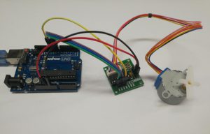
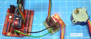
So, entering -1024 will make the motor to rotate half the way in anti-clock wise direction. Each channel of the module can deliver up to 2A to the stepper motor. If you cant find the datasheet, use the following trick. A Stepper Motor is abrushless, synchronous motor which completesa full rotation into a number of steps.In this Arduino stepper motor tutorial we will learn about the most commonly available stepper motor 28-BYJ48 and how to interface it with Arduino using ULN2003 stepper motor module. The best way to do this is to check the motors datasheet. Pink/Purple - Pin 9 So every NEMa17 I come across has a operational voltage of around 3V. The stepper library comes packaged with the Arduino IDE and takes care of the sequencing of the pulses that are sent to the motor. I am planning to use this for a project which requires a tiny space and it would be preferable for me to be able to only have 1 wire going in to power the circuit rather than 2. stepper arduino 5v arduino stepper 28byj The PCB quality are clean and brilliant. It can power up to 3 A4988 drivers, a bluetooth driver (HC-05) and one or two low power I2C devices as well as the MCU. Open the Arduino IDE software on your computer.
If you have any doubts post them on the comment section below our on our forums., #include  What will damage the motor is current (Amperes). IP22 rated medical & home-healthcare 18/24/36W AC-DC adaptors with interchangeable AC plugs. stepper code arduino motors drive transistor Next, we need to supply 5V to the logic circuitry of the L298N. To energise the four coils of the stepper motor we are using the digital pins 8,9,10 and 11. The way you pulse these pins affects the behavior of the motor. The circuit Diagram for the arduinostepper motor control project is shown above. Polarity doesnt matter. Share the Joy of learning with us. Therefore we need Stepper Driver Module like A4988 or DRV8825. // create ezButton object that attach to pin A0; // without this part, the move will stop after reaching maximum position, // if motor moved to the maximum position, // move the motor to maximum position again, // without calling stepper.run() function, motor stops immediately, // NOTE: stepper.stop() function does NOT stops motor immediately. If the wiring is correct, you will see the motor rotates clockwise direction. At the center of the module is a big, black chip with a chunky heat sink the L298N, from ST Semiconductor. In our case it is 200. arduino wiring stepper diagram uno bipolar motor circuit using bridge tutorial examples cc driver fritzing drive example driving control 12v
 As the name suggests it is the number of steps per revolution that your motor is rated at. Can you clarify what capacitor should be used for the 5v power supply? Please note that step() is a blocking function. Orange - Pin 11, Submitted by Aswinth Raj on Wed, 03/07/2018 - 11:30, In reply to Circuit Diagram is Incorrect by Michael MacDonald. Then, we also know that it is a four phase stepper motor since it had four coils in it. Let us take a look at the coils present inside the motor to know exactly know from where these wires come from. DO you need to download the stepper.h file my code wont compile. Thus, we can control the stepper motor with just 2 pins from our controller. Submitted by Manuel on Sat, 04/14/2018 - 21:38. Please take a close look at this Arduino - Stepper Motor tutorial to see how to connect the stepper motor to the L298N motor driver. arduino motor stepper It looks like the speed can range between 0 to 1000 for 28-BYJ48 stepper motors. Yellow - Pin 10 Stepper motors can turn an exact amount of degrees (or steps) as desired. Stepper motors are increasingly taking its position in the world of the electronics. It also supports multiple simultaneous steppers, with independent concurrent stepping on each stepper. Blue - Pin 8 kind regards, With 15 different sizes, aluform enclosures provide customers a wide range of potential uses. The methods described here can be used to infer how to use other motors and drivers which are not mentioned in this tutorial. Thank you! If you are planning on assembling your new robot, you will eventually want to learn how to control stepper motors. The following animation shows how H-bridges drive a stepper motor. stepper easydriver I then moved the wires around to follow the one in the real pictures of the circuit and it worked. It can be enabled or disabled via a jumper. Unlike a brushless DC motor, which rotates continuously when a fixed DC voltage is applied to it, a step motor rotates in discrete step angles. There is no technical reason for this motor for being named so; maybe we should dive much deeper into it. The direction -> ANTI-CLOCKWISE Black, Yellow, Green wires are part of the first winding while Red, White, and Blue is part of the second winding. Serial.begin(9600); Small current from Arduino becomes big current for the motor. stepper.setSpeed(200); We appreciate it. Is there any chance you could please list the shield's IN pin number to the Arduino pin number (i.e. In this case, the 5V input terminal (VSS) acts as the output pin and delivers 5V 0.5A. Thanks for pointing it out Michael, and sorry for the mistake. There are several ways to make a stepper motor stop: The below code make a stepper motor spin infinitely and stop immediately when a limit switch is touched. If you buy the components through these links, We may get a commission at no extra cost to you. // step one revolution in the other direction: Controlling a Stepper Motor With an HBridge, Identifying the Phases of a Bipolar Stepper Motor, Wiring a Bipolar Stepper Motor to the L298N Module and Arduino, Arduino Code - Controlling NEMA 17 Stepper Motor. Submitted by Michael MacDonald on Tue, 03/06/2018 - 06:59, The circuit diagram is incorrect. I think about setSpeed, moveTo, setAcceleration, setMaxSpeed or clockwise. Arduino can provide only about 20ma per output in, and thiw is not enough to move the more than 50 times higher current for the motor. You will see the stepper motor's direction is changed to the anti-clockwise, You will see the stepper motor's direction is changed to clockwise, The limit switch: TOUCHED This sketch will give you a complete understanding on how to control a bipolar stepper motor like NEMA 17 with L298N motor driver and can serve as a basis for more practical experiments and projects. I used D2 & D3 pins to control the motor direction and step. Lets start by connecting the power supply to the module. Pulling this pin LOW puts the driver in sleep mode, minimizing the facility consumption.
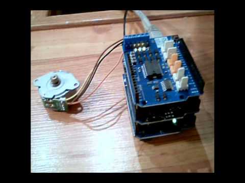
still the only thing I can find is people driving it with 12V and a A4988. stepper lesson In the setup section of the code, we set the speed of the stepper motor by calling the setSpeed() function and initialize the serial communication. Another important data to notice is the Stride Angle: 5.625/64. The connection diagram is given below. Power Supply Pins: The pin include VDD & VMOT & Pair of GND pins. When the jumpers are in place, the motor is enabled. Control Input Pins: STEP & DIR are the 2 control input pins. Most stepper motors will operate only with the help of a driver module. your assistance will be greatly appreciated. You can connect any 12-24V stepper motor to these terminals. The L298N motor driver has a supply range of 5V to 35V and is capable of supplying 2A continuous current per coil, so it works very well with most of our stepper motors. STEP input controls the micro-steps of the motor whereas DIR input controls the spinning direction of the motor. The driver module is powered by the 5V pin of the Arduino Board. Image is developed using Fritzing. As discussed earlier we will have to make 2048 steps to make one complete rotation, so when we enter 2048 the motor will make one complete rotation in clockwise direction by making 2048 steps. The stepper motor is STOPPED These pins actually control the switches of the H-Bridge circuit inside the L298N chip. The direction -> ANTI-CLOCKWISE The A4988 is a micro-stepping driver for controlling bipolar stepper motors which have a built-in translator for easy operation. We will be using the on-board 5V regulator to derive 5V from the motor power supply, so leave the 5V-EN jumper in place.
So, entering -1024 will make the motor to rotate half the way in anti-clock wise direction. Each channel of the module can deliver up to 2A to the stepper motor. If you cant find the datasheet, use the following trick. A Stepper Motor is abrushless, synchronous motor which completesa full rotation into a number of steps.In this Arduino stepper motor tutorial we will learn about the most commonly available stepper motor 28-BYJ48 and how to interface it with Arduino using ULN2003 stepper motor module. The best way to do this is to check the motors datasheet. Pink/Purple - Pin 9 So every NEMa17 I come across has a operational voltage of around 3V. The stepper library comes packaged with the Arduino IDE and takes care of the sequencing of the pulses that are sent to the motor. I am planning to use this for a project which requires a tiny space and it would be preferable for me to be able to only have 1 wire going in to power the circuit rather than 2. stepper arduino 5v arduino stepper 28byj The PCB quality are clean and brilliant. It can power up to 3 A4988 drivers, a bluetooth driver (HC-05) and one or two low power I2C devices as well as the MCU. Open the Arduino IDE software on your computer.