This is a useful specification as it will allow you to select a suitable driver and power supply for your stepper motor. On their site us a chart with the pins to be inserted. Instead, the negative voltage is applied to the OTHER side of the coil. In the loop we read the potentiometer position by measuring the input voltage on the analog pin using the Arduino analogRead function.  Now a harness has different color and gage wire in them. Lets take a look at the pinout of the A4988 module before we put it to use: Starting from the top right and working down we see the following pins: Now looking down the other side of the A4988 module: The key thing to note here is that the A4988 only requires two inputs from the Arduino to control the stepper motor and does not need the Arduino to figure out the stepping logic. By precisely controlling the current in the coils the motor shaft can be made to move in discrete steps, as illustrated in the following diagrams: In the first diagram the coil at the top is energized by applying electricity in the polarity shown. The L298N module has a jumper to set its internal 5-volt logic circuits to use either an external power supply (jumper off) or to use a built-in voltage regulator and derive the 5-volts from the motor power supply (jumper on). If you are using absolute sensors such as magnetic sensors or hall sensors, once you have done the alignment procedure and once you have the motors zero electrical offset sensor direction you no longer need the full calibration sequence. The move() method executes the motion control loops of the algorithm. Download Free version or register for a Free Trial. This information will be used to drive the motor by creating an instance of the Stepper class called steppermotor with the pin sequence of 8,10, 9, 11. This Is the method I used in the video. thanks in advance . Hello, Pick what one and how many I need. Does anyone know about the Adafruit 16-channel PWM/Servo Shield, how it works? STEPS_PER_OUT_REV is the final output of the motor shaft after gear reduction. But like the UNL2003 it still require the Arduino to do all the motor sequencing. The inductance of each motor coils, measured in millihenries. 2. It is a 5 wireRead more , Hi, from little time I have discovered and I/you/they have been spellbound of the world CNC. The logic supply DC voltage (positive) . Ive been trying every library sketch and every google search for these motors I can, and each time it comes to turn CCW, it just vibrates, then continues CW again. Jos. Can anyone assist me? This is the amount that the shaft of the motor will spin for each individual full step, measured in degrees, In some stepper motors this is referred to as. Thanks to you Im starting to make some sense of it. The 28BYJ-48 is a 5-wire unipolar stepper motor that moves 32 steps per rotation internally but has a gearing system that moves the shaft by a factor of 64. Im in the process of making a solar tracker not with LDRs but with set elevation and azimuth positions given from the SunPos node in Node-Red via MQTT. This is an important specification as inductance will limit the maximum speed youll be able to efficiently drive your stepper at. Your input is always welcome. You can also feel free to change the pin numbers if you need to as there are no special requirements there, just be sure to alter the sketch to reflect those changes if you decide to do that. And also note that the motor power supply you use should match your motor requirements. If yours is 64 you could always use integers. These modules are very inexpensive and are very reliable and they can be used to control either two DC motors or one stepper motor. Its going really well thanks to you. As the stepper motors only support torque using voltage mode this function will read the current motor angle from the sensor, turn it into the electrical angle and transforms the q-axis Uq voltage command motor.voltage_q to the appropriate phase voltages ua, ub and uc which are set then set to the motor. See the position sensor docs for more info! I tried using A0 to A3 but did not got success. To pilot these motors I think about doing him/it with the program of pilotage DevCnc Foam, that Arduino a compatible R3 points out with this software. I am using TB6560 driver for my stepper which is similar to A4988 driver. A servo motor is unique in that its motor shaft can be moved to a precise angle, most servos only rotate 180 or 270 degrees although there are modified servos that can spin a full 360 degrees. In our next experiment we will use a dedicated motor controller. I am just beginning with all of this, with trying to make small brushless engines. The magnetized shaft is attracted to this coil and then locks into place. The rule of thumb is to divide all the P, I and D gains with the motor.phase_resistance value. Your good preparatory work will help me a lot to find a good start. It also creates a lot of confusion as you often hear people refer to a motor simply as a NEMA 17, which really only designates the size of the motor and not its other specifications such as voltage, current, step angle or even if it is bipolar or unipolar. I figured the best motor to use would be a lead-screw stepping motor, attached the shutter to actuate, but after watching your explanation Im unsure if I should go with a unipolar or bipolar, to me a unipolar seems easier to code as you can merely reverse the direction to close with a -(minus), instead of reversing polarity through a hat? How are you sir Demonstrates Two 28BYJ-48 Unipolar Steppers with ULN2003 Driver, #define motorPin18 // Blue - 28BYJ48 pin 1, #define motorPin29 // Pink - 28BYJ48 pin 2, #define motorPin310// Yellow - 28BYJ48 pin 3, #define motorPin411// Orange - 28BYJ48 pin 4, #define motorPin54 // Blue - 28BYJ48 pin 1, #define motorPin65 // Pink - 28BYJ48 pin 2, #define motorPin76 // Yellow - 28BYJ48 pin 3, #define motorPin87 // Orange - 28BYJ48 pin 4, // The sequence 1-3-2-4 is required for proper sequencing of 28BYJ48, Demo 3 Bipolar Stepper with L298N H-Bridge, Demonstrates NEMA 17 Bipolar Stepper with L298N Driver, // Connected to L298N Motor Driver In1, In2, In3, In4, // Pins entered in sequence 1-2-3-4 for proper step sequencing. hohm.michel@free.fr The second run turns the motor clockwise a half turn very slowly. My appreciation to the dronebot team for creating such a useful resource. Unipolar stepper motors are easier to control as there is no requirement to reverse current polarity to change direction. The physical shape of the motor shaft. So, figure out the amperage of your motor, please! Ok so there are 27 spools of wire that I need to measure and cut. Again you should set this to match your stepper motor specifications. We will be using the same H-Bridge controller that we used in the previous article, the L298N module. A negative voltage is then applied to one side of the coil to attract the motor shaft, as illustrated below: As with the bipolar motor, the unipolar stepper motor can be made to advance one step when current is removed from the top coil and applied to one side of the second coil: You can also microstep a unipolar stepper motor by using the same technique that we used with bipolar steppers, applying current to both coils. I am working on a similar project that will also include a switch. In this tutorial we will learn how to move a stepper motor for a certain amount of steps, and then with a push of a button repeat it again.Watch the Video! For this design I would definitely use stepper drivers like the A4988 or the Easydriver,these would only require two pins for each motor but as you are probably always running the motors in the same direction (at least I assume you would be if I understand your application correctly) you would only need one. , Good Day Sir My challenges are the wiring since I know nothing about wiring boards, but I am trying. But as a hobbyist, without sponsorship, I often have to buy a Chinese product, cheaper, and this often comes without datasheet or any documentation at all.
It is interesting to observe the LEDs on the UNL2003 as this runs. They are used in 3D printers to position the printhead correctly and in CNC machines where their precision is used to position the cutting head. Step Angle: This is the amount that the shaft of the motor will spin for each individual full step, measured in degrees, In some stepper motors this is referred to as Steps Per Revolution and the two figures are just different ways of expressing the same thing. Here is how I have hooked up my L298N H-Bridge, bipolar stepper, and Arduino Uno: Note that you may not need to make all of these connections, this depends upon how you configure your L298N module. Finally, this parameter is suggested to be used if one whats to switch in real time in between voltage (voltage mode) and current based (DC current and FOC current) torque control strategies. The NEMA 17 sized stepper motor has become extremely popular, especially in the construction of 3D printers. Connect Stepper Motor to Arduino and control it with Rotary Encoder - Quick and Easy! If the stepper motors phase resistance and KV rating are provided this function will furthermore calculate the estimated current and the user will be able to control this estiamted current value Iq directly. It is set to A0. As you can see an L298N makes a great stepper motor controller as well as a DC motor controller. I was having issues with winding the copper coils so I decided to make an automatic coil winder with Arduino Nano and two stepper, one for winding, and the other to move the coil back and forth for even winding. In most configurations, a positive voltage is applied to the center tap and left there. motor control stepper should them type project use tilt camera horizontal ll pan rotation need I have already watched a lot of your videos and maybe thereRead more . Your post will be seen not only by myself, but by a large group of tech enthusiasts who can quickly answer your question. Hi, Im trying to do something similar but Im having trouble with the digital pins from the Mega (14-53). The Arduino runs the code in the Setup function first, so anything you put in there runs once. : This is the amount of holding torque that can be expected when the motor is NOT energized. is a very common and inexpensive stepper motor controller that is used a lot in 3D printers and CNC machines where several stepper motors need to be managed. This is done by controlling the ratio of the current applied to both coils to attract the motor shaft to a position between the coils but closer to one coil than the other. The stepper in question is a STP-42D221-03 stepper from an old dot matrix printer. This can either be done in hardware or in firmware (e.g. So we define three constants to handle motor rotation: In case you are wondering why a float was used instead of an integer for the above constants, its because the gear reduction is sometimes a number like 63.5. OK, enough theory! Your tutorials and videos have been so helpful..I read a few books, but to be quite honest they are no subtitute for a video tuturorial. If you feel like a challenge you can rewrite it to use the AccelStepper library instead. If you choose not to set some of the configuration parameters they will take values defined in the defaults.h file. The DRV8860 has several operating modes; you only need to implement the default operating mode. Any ideas as to how to solve the problem and remove the error message? But here is where I got lost a little. Keep the videos and tuturials coming Bill. Time to dig out our Arduino and start experimenting with stepper motors. This is an active low connection, when brought low (ground) the A4988 module is enabled. Hi PDF Version A PDF version of this article, great for printing and using on your workbench. We will do two things here, spin the motor slowly clockwise one turn and then spin it counterclockwise two turns. The motor is trying to spin the right direction however it only vibrate (mostly) and does not work fine. Write an Arduino program that uses a single Texas Instruments DRV8860 to turn two unipolar stepper motors in one direction (clockwise or counter clockwise, your choice) simultaneously. And the final run returns the motor a half turn at a much faster speed. Im working on a robot arm project using servo motors and the PCA9685 at the moment. Were going to fire just a single phase at a time; this is probably the simplest method but its likely the least used because the other two methods have some advantages but with wave driving again were only going to fire a single phase at a time, so if I look through this diagram on the top in any one time slice so with step one just the blue phases energized then just the pink phase then just the yellow then just the orange so theres really four phases in this cycle here and then I just repeat blue-pink-yellow-orange; Lets now have a little practice:) Use your ULN2003 BOARD this way: Please see this post for more information: Full stepping is going to give me the same step angle as wave driving so Im going to get the same precision with the full step as I do with wave drive but Im going to get double the torque because with full stepping were actually going to energize two phases at a time so at any one given time slice; here two phases are energized; first the blue and the pink then the pink and the yellow then the yellow and orange then the blue and the orange; so thats a single cycle through those four phases and then again I repeat blue and pink yellow pink yellow orange orange and blue. do i need? The older members among you can still remember DVD-ROM drives well: let's take another look at the inner values of a past technology. An excellent article about stepper motors from Adafruit. What components will he use?
The first one, my A4988 is getting hot, really hot ! Steppers, on the other hand, are unaware of their position. James Cullins. The pulses are manually generated in a very similar fashion as the Arduino Blink sketch, by bringing the output HIGH, waiting a bit then Bringing it LOW and waiting again. It is also a function of the current rating and the coil resistance and you can use Ohms Law to calculate one from the other. We also define STEPS_PER_REV as we did in the previous sketch, the number of steps our motor needs to complete one rotation. Thanks a lot ! After much observation, I think I came to the pattern of how to discover the ends of the motor's coils. Is there a way to know a stepper motor is pointing? This time well swap out the rotary encoder with an ordinary potentiometer and use that to control either the position or speed of the stepper motor. that depends on how you translate the rotation movement to a linear movement, does not have much to do with the motor.. Im trying Demo !
Congratulations! could i run this motor without generating code ? Hello all I am currently in the design phase in an automatic wire cutter for work. And that is it, you have your complete Field Oriented Controlled BLDC motor with motion control. They also pack a lot of torque into a comparably small package. Thanks for these tutorials.
The maximum voltage is 35 volts. This is essentially a P-controller where we find a difference (pos_error) between the actual position (actual_pos) and the target position (target_pos) and use this to control the motor. A unipolar stepper motor also consists of two coils (electrically) but each coil has a center tap so there are three connections on each coil. You will need to know this in order to mate your stepper motor with gears, pulleys and other external connections such as shaft couplers. Please let me know in the comments about any problems or observations you encounter using stepper motors. Current: The maximum current at the rated voltage. That is without anything connection to the direction and steps pins on the A4988. This makes it a lot easier to control multiple stepper motors for advanced projects. The Loop is a special function, any code in there runs and then repeats itself until the Arduino is powered off or reset. Detent Torque: This is the amount of holding torque that can be expected when the motor is NOT energized. Could you please guide me what changes should I make in the code for using Tb-6560 with potentiometer. Does a capacitors marked voltage matter? Any ideas how to solve this ?
This is essential to decouple the power supply. I have a query similar to Robins, where I want to trigger a stepper motor to run by an input pulse to the Arduino (for the stepper to run X amount of steps (say 200), until the Arduino receives another pulse to move an equal number of (200) steps & so on, until a preset (programmed) number of cycles has been completed), then I want the stepper motor to reverse, and go an equal amount of steps in the reverse direction, and repeat the above cycle.Read more , Great study, I follow it, was wonderful, keep it up. I would love to build a control for a model train turntable where I could tell it to go to a specific degree or location to line up the tracks(Hint). The principle can be extended to include quarter steps, eight steps, and even sixteenth steps. Code for this article All of the Arduino Sketches used in this article in one ZIP file. We have discussed using an H-Bridge before when we talked about controlling brushed DC Motors. This code doesnt perform any calibration, but rather just assume that both the motor and the pot is centered at system start. The motor DC supply voltage (positive). Note that the second motor has a negative number of steps, this indicates it is to move counterclockwise when it is initialized. If you are using spindles for example,, the spindle specification will have a number (ex:5mm) for full rotation.. Then if you are using a 1.8 motor, then yopu need 200 steps for 360. Download Free version or register for a Free Trial. That will be a good staring point. This is repeated as many times as necessary to rotate our motor oin the amount we desire, one full rotation for the first routine and two rotations for the second one. By setting the logic levels here you can set the motor to Full, Half, Quarter, Eighth or Sixteenth steps. Next we set up two motor objects, one for each motor. These design differences primarily deal with the method employed to create the magnetic field within the motor. Demonstrates 28BYJ-48 Unipolar Stepper with ULN2003 Driver, // Number of steps per internal motor revolution, // Number of steps per geared output rotation, // Connected to ULN2003 Motor Driver In1, In2, In3, In4, // Pins entered in sequence 1-3-2-4 for proper step sequencing, // Nothing(Stepper Library sets pins as outputs), // Slow - 4-step CW sequence to observe lights on driver board. and the two figures are just different ways of expressing the same thing. The result is that the motor speed will be controlled by the potentiometer. As an example, a common rating for a stepper motor is a 1.8-degree step angle. After the position sensor, driver and the motor are configured, and before we can start the motion control we need to align all hardware components in order to initialize the FOC algorithm. These variables are used to estimate the motor current in the voltage torque mode and for open-loop motion control. The 28BYJ-48 runs on 5 volts. For this experiment, I used a NEMA 17 sized bipolar stepper rated at 12 volts but any bipolar stepper motor can be used as long as you observe the voltage ratings and use a suitable power supply. How can i relate the step according to distance? also needs to be installed. SPEED_CONTROL is the analog port we connect the potentiometer. To browse Academia.edu and the wider internet faster and more securely, please take a few seconds toupgrade your browser. Start Visuino as shown in the first picture Click on the "Tools" button on the Arduino component (Picture 1) in Visuino When the dialog appears, select "Arduino UNO" as shown on Picture 2. Another advantage stepper motors have over DC motors is the ability to move art very slow speeds without stalling, in fact, stalling really isnt a concept with stepper motors. As long as it is over zero we set the motor speed and then step it one one hundredth of a revolution, which in the case of my motor will move it two steps or 3 degrees. Make sure you get this right or the motor will not operate properly. My question is, how do we use a potentiometer to control the speed of the stepper? Demo 2 Two 28BYJ-48 Unipolar Steppers with ULN2003. You should be aware of how potentiometers work prior to reading this post.
Hello, Note that one motor is running at full steps while the other uses half steps, observe the lights on the UNL2003 controller when the motors start and stop and youll notice a difference in the step patterns. This is done in the scope of the funciton motor.initFOC(). Thank you soRead more . Got it!!!! i would like to please use a stepper motor for a turntable. Actually tested it with about 9 different A4988 drivers and still the same thing. The sensor will be used to determine electrical position of the motor for the FOC algorithm as well as for the motion control loops of velocity and position. Typically unipolar stepper motors have an advantage here as they only use half a coil and thus have lower inductance than their bipolar equivalents. Move the code to void setup? Many first time users are scared off by the vast number of specifications included with some stepper motors. Mine was rated at 200, which is the same as 1.8 degrees per step. The diagrams are simplified for clarity). Hopefully this article and the accompanying video have shown you that stepper motors are not really that hard to work with after all. Also when its supposed to make a full rotation, its only doing like a quarter one. I would like to rotate the turntable table by 360 on the number of days in a month in one clockwise direction. If is governed by the motor.controller variable. Half stepping changes that to 64 steps of 5.625 each for a full rotation. Inductance: The inductance of each motor coils, measured in millihenries. Of course you can add as many routines as you wish to make your motor move in the speed and direction you like. Usually, these types of motors the wires leave the motor in pairs and the other end of the wire appears in the firing sequence. Distributed Computing from a different dimension, 2 Simple Solutions to Fix Missed Dependencies of a Go Module, C programming: A modern approach books solution || chapter 1 solution of c programming a modern, How user testing refines our pattern library development, How PBS is Enabling Apples Trick Play Mode, Dab Detector usingPython(with visualization), Fast IO and tips for competitive programming using python, 28BYJ-48 Stepper Motor and ULN2003 Driver Intro, http://blog.inventables.com/p/stepper-motors.html, The Maker Show: Episode 8 Driving Your Stepper Motor with an Arduino, eet DoRobot Assembly Techniques J3 Caterpillar-Crawler-Chassis v 1.0 ArduSerie#46. though I would like to ask you and the general forum maybeRead more . By default this is pulled low so the module is always enabled unless you apply a logic high here.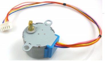 Simply the voltage rating of the motor coils. There are a group of stepper motors that have standard sizes, we will look at these now. In this demonstration, we will drive one motor at full steps and the second one at half steps. However, due to the large volume of comments that I receive, it may not be possible for me to answer you directly here on the website. In actual fact, they are not that difficult to understand. How to make coil winding machine CNC automatically, Where do i read about how to get the code into the Arduino, Hello, I have set this up correctly, but the set-up with the A4988 on my end has some sort of trouble that I might need help with. The connections to coil 2 of the bipolar stepper motor. Once you know that you can just count the steps and do the math to determine the position of the shaft. Because the move in discrete steps a stepper motor is not often used where a smooth continuous rotation is required, However with the use of gearing and microstepping they can approach a smooth rotation and their ability to be very accurately positioned often outweighs the roughness of their movement. ), Hi there, I am having problem with my Arduino Uno and CNC shiled, recently I have tried all these workshop tutorial with the 28BYJ-48 stepper motor, and everything worked good, then i am trying to use to A4988 driver with CNC shield to move my stepper motor for my small project like writing plotter I am using GRBL V.9j on Arduino to control my stepper motor, when I setup all the component everything work fine then all of sudden when i move any of axis using Grbl controller g code software both axis move at the same time, i triedRead more . I think that somehow there is interference of some sort and if I disconnect them and leave only the 5V power from the Arduino connected as in the example on this page, the stepper motor starts moving smoothly in 1 direction. Just a silly mistake staring me in the face that I could not see for two days, HI, and first, thank you for that tutorial, i need to drive this motor , by half steps, with an arduino, i already have a UNO model , which shield/driver and power supply (24v?) Connect "PulseGenerator1" pin [Out] to "UpDownCounter1" pin [Down], Connect "Button1" pin [Out] to "UpDownCounter1" pin [Reset], Connect "UpDownCounter1" pin [Out] to "Stepper1" pin [In], Connect "Stepper1" pin [0] to Arduino digital pin [4], Connect "Stepper1" pin [1] to Arduino digital pin [5], Connect "Stepper1" pin [2] to Arduino digital pin [6], Connect "Stepper1" pin [3] to Arduino digital pin [7], Connect Arduino Digital pin [2] to "Button1" pin [In]. This is set at 32. The shaft is attracted to the second coil and locks into place there. That was very good and easy to understand, Thank you for an excellent video on steppers. Everything else is wired as per the example above and already tested the nema 17 with another L298N andRead more , Just an update, noticed that if I have the Arduino Mega and the A4988 powered and the wires I have from the Pins on the Steps and Direction on the A4988 are messing up the vibration if I touch them. The maximum current at the rated voltage. You will need to install this library using the Arduino IDE Library Manager as it is not included in the Arduino IDE. I am really surprised toRead more . You can also get a shield for your Arduino that allows you to drive multiple A4988 modules, which would be great if you are building a CNC machine or a 3D printer. The real-time motion control of theArduino SimpleFOClibrary is realized with two functions: The function loopFOC() implements the torque control loop. You actually can control the motor without a microcontroller, a simple square wave oscillator can suffice in many situations. A stepper motor may have several coils but they are wired together and controlled in phases. The faster you pulse this the faster the motor will travel. You will need to know this in order to mate your stepper motor with gears, pulleys and other external connections such as shaft couplers. Essentially this is a device that contains four internal power transistors that allow control of the direction of current through a motor coil. In my 3d printer Ive replaced all the A4988s for TMC2208 and change nothing else. Hello! Any thoughts? Hi I have this stepper motor nema 23 connected to my x axis of my milling machine .
Now a harness has different color and gage wire in them. Lets take a look at the pinout of the A4988 module before we put it to use: Starting from the top right and working down we see the following pins: Now looking down the other side of the A4988 module: The key thing to note here is that the A4988 only requires two inputs from the Arduino to control the stepper motor and does not need the Arduino to figure out the stepping logic. By precisely controlling the current in the coils the motor shaft can be made to move in discrete steps, as illustrated in the following diagrams: In the first diagram the coil at the top is energized by applying electricity in the polarity shown. The L298N module has a jumper to set its internal 5-volt logic circuits to use either an external power supply (jumper off) or to use a built-in voltage regulator and derive the 5-volts from the motor power supply (jumper on). If you are using absolute sensors such as magnetic sensors or hall sensors, once you have done the alignment procedure and once you have the motors zero electrical offset sensor direction you no longer need the full calibration sequence. The move() method executes the motion control loops of the algorithm. Download Free version or register for a Free Trial. This information will be used to drive the motor by creating an instance of the Stepper class called steppermotor with the pin sequence of 8,10, 9, 11. This Is the method I used in the video. thanks in advance . Hello, Pick what one and how many I need. Does anyone know about the Adafruit 16-channel PWM/Servo Shield, how it works? STEPS_PER_OUT_REV is the final output of the motor shaft after gear reduction. But like the UNL2003 it still require the Arduino to do all the motor sequencing. The inductance of each motor coils, measured in millihenries. 2. It is a 5 wireRead more , Hi, from little time I have discovered and I/you/they have been spellbound of the world CNC. The logic supply DC voltage (positive) . Ive been trying every library sketch and every google search for these motors I can, and each time it comes to turn CCW, it just vibrates, then continues CW again. Jos. Can anyone assist me? This is the amount that the shaft of the motor will spin for each individual full step, measured in degrees, In some stepper motors this is referred to as. Thanks to you Im starting to make some sense of it. The 28BYJ-48 is a 5-wire unipolar stepper motor that moves 32 steps per rotation internally but has a gearing system that moves the shaft by a factor of 64. Im in the process of making a solar tracker not with LDRs but with set elevation and azimuth positions given from the SunPos node in Node-Red via MQTT. This is an important specification as inductance will limit the maximum speed youll be able to efficiently drive your stepper at. Your input is always welcome. You can also feel free to change the pin numbers if you need to as there are no special requirements there, just be sure to alter the sketch to reflect those changes if you decide to do that. And also note that the motor power supply you use should match your motor requirements. If yours is 64 you could always use integers. These modules are very inexpensive and are very reliable and they can be used to control either two DC motors or one stepper motor. Its going really well thanks to you. As the stepper motors only support torque using voltage mode this function will read the current motor angle from the sensor, turn it into the electrical angle and transforms the q-axis Uq voltage command motor.voltage_q to the appropriate phase voltages ua, ub and uc which are set then set to the motor. See the position sensor docs for more info! I tried using A0 to A3 but did not got success. To pilot these motors I think about doing him/it with the program of pilotage DevCnc Foam, that Arduino a compatible R3 points out with this software. I am using TB6560 driver for my stepper which is similar to A4988 driver. A servo motor is unique in that its motor shaft can be moved to a precise angle, most servos only rotate 180 or 270 degrees although there are modified servos that can spin a full 360 degrees. In our next experiment we will use a dedicated motor controller. I am just beginning with all of this, with trying to make small brushless engines. The magnetized shaft is attracted to this coil and then locks into place. The rule of thumb is to divide all the P, I and D gains with the motor.phase_resistance value. Your good preparatory work will help me a lot to find a good start. It also creates a lot of confusion as you often hear people refer to a motor simply as a NEMA 17, which really only designates the size of the motor and not its other specifications such as voltage, current, step angle or even if it is bipolar or unipolar. I figured the best motor to use would be a lead-screw stepping motor, attached the shutter to actuate, but after watching your explanation Im unsure if I should go with a unipolar or bipolar, to me a unipolar seems easier to code as you can merely reverse the direction to close with a -(minus), instead of reversing polarity through a hat? How are you sir Demonstrates Two 28BYJ-48 Unipolar Steppers with ULN2003 Driver, #define motorPin18 // Blue - 28BYJ48 pin 1, #define motorPin29 // Pink - 28BYJ48 pin 2, #define motorPin310// Yellow - 28BYJ48 pin 3, #define motorPin411// Orange - 28BYJ48 pin 4, #define motorPin54 // Blue - 28BYJ48 pin 1, #define motorPin65 // Pink - 28BYJ48 pin 2, #define motorPin76 // Yellow - 28BYJ48 pin 3, #define motorPin87 // Orange - 28BYJ48 pin 4, // The sequence 1-3-2-4 is required for proper sequencing of 28BYJ48, Demo 3 Bipolar Stepper with L298N H-Bridge, Demonstrates NEMA 17 Bipolar Stepper with L298N Driver, // Connected to L298N Motor Driver In1, In2, In3, In4, // Pins entered in sequence 1-2-3-4 for proper step sequencing. hohm.michel@free.fr The second run turns the motor clockwise a half turn very slowly. My appreciation to the dronebot team for creating such a useful resource. Unipolar stepper motors are easier to control as there is no requirement to reverse current polarity to change direction. The physical shape of the motor shaft. So, figure out the amperage of your motor, please! Ok so there are 27 spools of wire that I need to measure and cut. Again you should set this to match your stepper motor specifications. We will be using the same H-Bridge controller that we used in the previous article, the L298N module. A negative voltage is then applied to one side of the coil to attract the motor shaft, as illustrated below: As with the bipolar motor, the unipolar stepper motor can be made to advance one step when current is removed from the top coil and applied to one side of the second coil: You can also microstep a unipolar stepper motor by using the same technique that we used with bipolar steppers, applying current to both coils. I am working on a similar project that will also include a switch. In this tutorial we will learn how to move a stepper motor for a certain amount of steps, and then with a push of a button repeat it again.Watch the Video! For this design I would definitely use stepper drivers like the A4988 or the Easydriver,these would only require two pins for each motor but as you are probably always running the motors in the same direction (at least I assume you would be if I understand your application correctly) you would only need one. , Good Day Sir My challenges are the wiring since I know nothing about wiring boards, but I am trying. But as a hobbyist, without sponsorship, I often have to buy a Chinese product, cheaper, and this often comes without datasheet or any documentation at all. It is interesting to observe the LEDs on the UNL2003 as this runs. They are used in 3D printers to position the printhead correctly and in CNC machines where their precision is used to position the cutting head. Step Angle: This is the amount that the shaft of the motor will spin for each individual full step, measured in degrees, In some stepper motors this is referred to as Steps Per Revolution and the two figures are just different ways of expressing the same thing. Here is how I have hooked up my L298N H-Bridge, bipolar stepper, and Arduino Uno: Note that you may not need to make all of these connections, this depends upon how you configure your L298N module. Finally, this parameter is suggested to be used if one whats to switch in real time in between voltage (voltage mode) and current based (DC current and FOC current) torque control strategies. The NEMA 17 sized stepper motor has become extremely popular, especially in the construction of 3D printers. Connect Stepper Motor to Arduino and control it with Rotary Encoder - Quick and Easy! If the stepper motors phase resistance and KV rating are provided this function will furthermore calculate the estimated current and the user will be able to control this estiamted current value Iq directly. It is set to A0. As you can see an L298N makes a great stepper motor controller as well as a DC motor controller. I was having issues with winding the copper coils so I decided to make an automatic coil winder with Arduino Nano and two stepper, one for winding, and the other to move the coil back and forth for even winding. In most configurations, a positive voltage is applied to the center tap and left there. motor control stepper should them type project use tilt camera horizontal ll pan rotation need I have already watched a lot of your videos and maybe thereRead more . Your post will be seen not only by myself, but by a large group of tech enthusiasts who can quickly answer your question. Hi, Im trying to do something similar but Im having trouble with the digital pins from the Mega (14-53). The Arduino runs the code in the Setup function first, so anything you put in there runs once. : This is the amount of holding torque that can be expected when the motor is NOT energized. is a very common and inexpensive stepper motor controller that is used a lot in 3D printers and CNC machines where several stepper motors need to be managed. This is done by controlling the ratio of the current applied to both coils to attract the motor shaft to a position between the coils but closer to one coil than the other. The stepper in question is a STP-42D221-03 stepper from an old dot matrix printer. This can either be done in hardware or in firmware (e.g. So we define three constants to handle motor rotation: In case you are wondering why a float was used instead of an integer for the above constants, its because the gear reduction is sometimes a number like 63.5. OK, enough theory! Your tutorials and videos have been so helpful..I read a few books, but to be quite honest they are no subtitute for a video tuturorial. If you feel like a challenge you can rewrite it to use the AccelStepper library instead. If you choose not to set some of the configuration parameters they will take values defined in the defaults.h file. The DRV8860 has several operating modes; you only need to implement the default operating mode. Any ideas as to how to solve the problem and remove the error message? But here is where I got lost a little. Keep the videos and tuturials coming Bill. Time to dig out our Arduino and start experimenting with stepper motors. This is an active low connection, when brought low (ground) the A4988 module is enabled. Hi PDF Version A PDF version of this article, great for printing and using on your workbench. We will do two things here, spin the motor slowly clockwise one turn and then spin it counterclockwise two turns. The motor is trying to spin the right direction however it only vibrate (mostly) and does not work fine. Write an Arduino program that uses a single Texas Instruments DRV8860 to turn two unipolar stepper motors in one direction (clockwise or counter clockwise, your choice) simultaneously. And the final run returns the motor a half turn at a much faster speed. Im working on a robot arm project using servo motors and the PCA9685 at the moment. Were going to fire just a single phase at a time; this is probably the simplest method but its likely the least used because the other two methods have some advantages but with wave driving again were only going to fire a single phase at a time, so if I look through this diagram on the top in any one time slice so with step one just the blue phases energized then just the pink phase then just the yellow then just the orange so theres really four phases in this cycle here and then I just repeat blue-pink-yellow-orange; Lets now have a little practice:) Use your ULN2003 BOARD this way: Please see this post for more information: Full stepping is going to give me the same step angle as wave driving so Im going to get the same precision with the full step as I do with wave drive but Im going to get double the torque because with full stepping were actually going to energize two phases at a time so at any one given time slice; here two phases are energized; first the blue and the pink then the pink and the yellow then the yellow and orange then the blue and the orange; so thats a single cycle through those four phases and then again I repeat blue and pink yellow pink yellow orange orange and blue. do i need? The older members among you can still remember DVD-ROM drives well: let's take another look at the inner values of a past technology. An excellent article about stepper motors from Adafruit. What components will he use?
The first one, my A4988 is getting hot, really hot ! Steppers, on the other hand, are unaware of their position. James Cullins. The pulses are manually generated in a very similar fashion as the Arduino Blink sketch, by bringing the output HIGH, waiting a bit then Bringing it LOW and waiting again. It is also a function of the current rating and the coil resistance and you can use Ohms Law to calculate one from the other. We also define STEPS_PER_REV as we did in the previous sketch, the number of steps our motor needs to complete one rotation. Thanks a lot ! After much observation, I think I came to the pattern of how to discover the ends of the motor's coils. Is there a way to know a stepper motor is pointing? This time well swap out the rotary encoder with an ordinary potentiometer and use that to control either the position or speed of the stepper motor. that depends on how you translate the rotation movement to a linear movement, does not have much to do with the motor.. Im trying Demo !
Congratulations! could i run this motor without generating code ? Hello all I am currently in the design phase in an automatic wire cutter for work. And that is it, you have your complete Field Oriented Controlled BLDC motor with motion control. They also pack a lot of torque into a comparably small package. Thanks for these tutorials.
The maximum voltage is 35 volts. This is essentially a P-controller where we find a difference (pos_error) between the actual position (actual_pos) and the target position (target_pos) and use this to control the motor. A unipolar stepper motor also consists of two coils (electrically) but each coil has a center tap so there are three connections on each coil. You will need to know this in order to mate your stepper motor with gears, pulleys and other external connections such as shaft couplers. Please let me know in the comments about any problems or observations you encounter using stepper motors. Current: The maximum current at the rated voltage. That is without anything connection to the direction and steps pins on the A4988. This makes it a lot easier to control multiple stepper motors for advanced projects. The Loop is a special function, any code in there runs and then repeats itself until the Arduino is powered off or reset. Detent Torque: This is the amount of holding torque that can be expected when the motor is NOT energized. Could you please guide me what changes should I make in the code for using Tb-6560 with potentiometer. Does a capacitors marked voltage matter? Any ideas how to solve this ?
This is essential to decouple the power supply. I have a query similar to Robins, where I want to trigger a stepper motor to run by an input pulse to the Arduino (for the stepper to run X amount of steps (say 200), until the Arduino receives another pulse to move an equal number of (200) steps & so on, until a preset (programmed) number of cycles has been completed), then I want the stepper motor to reverse, and go an equal amount of steps in the reverse direction, and repeat the above cycle.Read more , Great study, I follow it, was wonderful, keep it up. I would love to build a control for a model train turntable where I could tell it to go to a specific degree or location to line up the tracks(Hint). The principle can be extended to include quarter steps, eight steps, and even sixteenth steps. Code for this article All of the Arduino Sketches used in this article in one ZIP file. We have discussed using an H-Bridge before when we talked about controlling brushed DC Motors. This code doesnt perform any calibration, but rather just assume that both the motor and the pot is centered at system start. The motor DC supply voltage (positive). Note that the second motor has a negative number of steps, this indicates it is to move counterclockwise when it is initialized. If you are using spindles for example,, the spindle specification will have a number (ex:5mm) for full rotation.. Then if you are using a 1.8 motor, then yopu need 200 steps for 360. Download Free version or register for a Free Trial. That will be a good staring point. This is repeated as many times as necessary to rotate our motor oin the amount we desire, one full rotation for the first routine and two rotations for the second one. By setting the logic levels here you can set the motor to Full, Half, Quarter, Eighth or Sixteenth steps. Next we set up two motor objects, one for each motor. These design differences primarily deal with the method employed to create the magnetic field within the motor. Demonstrates 28BYJ-48 Unipolar Stepper with ULN2003 Driver, // Number of steps per internal motor revolution, // Number of steps per geared output rotation, // Connected to ULN2003 Motor Driver In1, In2, In3, In4, // Pins entered in sequence 1-3-2-4 for proper step sequencing, // Nothing(Stepper Library sets pins as outputs), // Slow - 4-step CW sequence to observe lights on driver board. and the two figures are just different ways of expressing the same thing. The result is that the motor speed will be controlled by the potentiometer. As an example, a common rating for a stepper motor is a 1.8-degree step angle. After the position sensor, driver and the motor are configured, and before we can start the motion control we need to align all hardware components in order to initialize the FOC algorithm. These variables are used to estimate the motor current in the voltage torque mode and for open-loop motion control. The 28BYJ-48 runs on 5 volts. For this experiment, I used a NEMA 17 sized bipolar stepper rated at 12 volts but any bipolar stepper motor can be used as long as you observe the voltage ratings and use a suitable power supply. How can i relate the step according to distance? also needs to be installed. SPEED_CONTROL is the analog port we connect the potentiometer. To browse Academia.edu and the wider internet faster and more securely, please take a few seconds toupgrade your browser. Start Visuino as shown in the first picture Click on the "Tools" button on the Arduino component (Picture 1) in Visuino When the dialog appears, select "Arduino UNO" as shown on Picture 2. Another advantage stepper motors have over DC motors is the ability to move art very slow speeds without stalling, in fact, stalling really isnt a concept with stepper motors. As long as it is over zero we set the motor speed and then step it one one hundredth of a revolution, which in the case of my motor will move it two steps or 3 degrees. Make sure you get this right or the motor will not operate properly. My question is, how do we use a potentiometer to control the speed of the stepper? Demo 2 Two 28BYJ-48 Unipolar Steppers with ULN2003. You should be aware of how potentiometers work prior to reading this post.
Hello, Note that one motor is running at full steps while the other uses half steps, observe the lights on the UNL2003 controller when the motors start and stop and youll notice a difference in the step patterns. This is done in the scope of the funciton motor.initFOC(). Thank you soRead more . Got it!!!! i would like to please use a stepper motor for a turntable. Actually tested it with about 9 different A4988 drivers and still the same thing. The sensor will be used to determine electrical position of the motor for the FOC algorithm as well as for the motion control loops of velocity and position. Typically unipolar stepper motors have an advantage here as they only use half a coil and thus have lower inductance than their bipolar equivalents. Move the code to void setup? Many first time users are scared off by the vast number of specifications included with some stepper motors. Mine was rated at 200, which is the same as 1.8 degrees per step. The diagrams are simplified for clarity). Hopefully this article and the accompanying video have shown you that stepper motors are not really that hard to work with after all. Also when its supposed to make a full rotation, its only doing like a quarter one. I would like to rotate the turntable table by 360 on the number of days in a month in one clockwise direction. If is governed by the motor.controller variable. Half stepping changes that to 64 steps of 5.625 each for a full rotation. Inductance: The inductance of each motor coils, measured in millihenries. Of course you can add as many routines as you wish to make your motor move in the speed and direction you like. Usually, these types of motors the wires leave the motor in pairs and the other end of the wire appears in the firing sequence. Distributed Computing from a different dimension, 2 Simple Solutions to Fix Missed Dependencies of a Go Module, C programming: A modern approach books solution || chapter 1 solution of c programming a modern, How user testing refines our pattern library development, How PBS is Enabling Apples Trick Play Mode, Dab Detector usingPython(with visualization), Fast IO and tips for competitive programming using python, 28BYJ-48 Stepper Motor and ULN2003 Driver Intro, http://blog.inventables.com/p/stepper-motors.html, The Maker Show: Episode 8 Driving Your Stepper Motor with an Arduino, eet DoRobot Assembly Techniques J3 Caterpillar-Crawler-Chassis v 1.0 ArduSerie#46. though I would like to ask you and the general forum maybeRead more . By default this is pulled low so the module is always enabled unless you apply a logic high here.
Simply the voltage rating of the motor coils. There are a group of stepper motors that have standard sizes, we will look at these now. In this demonstration, we will drive one motor at full steps and the second one at half steps. However, due to the large volume of comments that I receive, it may not be possible for me to answer you directly here on the website. In actual fact, they are not that difficult to understand. How to make coil winding machine CNC automatically, Where do i read about how to get the code into the Arduino, Hello, I have set this up correctly, but the set-up with the A4988 on my end has some sort of trouble that I might need help with. The connections to coil 2 of the bipolar stepper motor. Once you know that you can just count the steps and do the math to determine the position of the shaft. Because the move in discrete steps a stepper motor is not often used where a smooth continuous rotation is required, However with the use of gearing and microstepping they can approach a smooth rotation and their ability to be very accurately positioned often outweighs the roughness of their movement. ), Hi there, I am having problem with my Arduino Uno and CNC shiled, recently I have tried all these workshop tutorial with the 28BYJ-48 stepper motor, and everything worked good, then i am trying to use to A4988 driver with CNC shield to move my stepper motor for my small project like writing plotter I am using GRBL V.9j on Arduino to control my stepper motor, when I setup all the component everything work fine then all of sudden when i move any of axis using Grbl controller g code software both axis move at the same time, i triedRead more . I think that somehow there is interference of some sort and if I disconnect them and leave only the 5V power from the Arduino connected as in the example on this page, the stepper motor starts moving smoothly in 1 direction. Just a silly mistake staring me in the face that I could not see for two days, HI, and first, thank you for that tutorial, i need to drive this motor , by half steps, with an arduino, i already have a UNO model , which shield/driver and power supply (24v?) Connect "PulseGenerator1" pin [Out] to "UpDownCounter1" pin [Down], Connect "Button1" pin [Out] to "UpDownCounter1" pin [Reset], Connect "UpDownCounter1" pin [Out] to "Stepper1" pin [In], Connect "Stepper1" pin [0] to Arduino digital pin [4], Connect "Stepper1" pin [1] to Arduino digital pin [5], Connect "Stepper1" pin [2] to Arduino digital pin [6], Connect "Stepper1" pin [3] to Arduino digital pin [7], Connect Arduino Digital pin [2] to "Button1" pin [In]. This is set at 32. The shaft is attracted to the second coil and locks into place there. That was very good and easy to understand, Thank you for an excellent video on steppers. Everything else is wired as per the example above and already tested the nema 17 with another L298N andRead more , Just an update, noticed that if I have the Arduino Mega and the A4988 powered and the wires I have from the Pins on the Steps and Direction on the A4988 are messing up the vibration if I touch them. The maximum current at the rated voltage. You will need to install this library using the Arduino IDE Library Manager as it is not included in the Arduino IDE. I am really surprised toRead more . You can also get a shield for your Arduino that allows you to drive multiple A4988 modules, which would be great if you are building a CNC machine or a 3D printer. The real-time motion control of theArduino SimpleFOClibrary is realized with two functions: The function loopFOC() implements the torque control loop. You actually can control the motor without a microcontroller, a simple square wave oscillator can suffice in many situations. A stepper motor may have several coils but they are wired together and controlled in phases. The faster you pulse this the faster the motor will travel. You will need to know this in order to mate your stepper motor with gears, pulleys and other external connections such as shaft couplers. Essentially this is a device that contains four internal power transistors that allow control of the direction of current through a motor coil. In my 3d printer Ive replaced all the A4988s for TMC2208 and change nothing else. Hello! Any thoughts? Hi I have this stepper motor nema 23 connected to my x axis of my milling machine .